

The name is often abbreviated to MICC or MI cable, and colloquially known as pyro. A similar product sheathed with metals other than copper is called mineral insulated metal sheathed (MIMS) cable.
What is MICC/Pyro cable used for?
Pyrosales works with Mineral Insulated Cable Co., Ltd. to supply MICC wiring cable systems. The main function of MICC cable is to ensure during a fire that all the building emergency and essential circuits such as escape lighting, fire sensors, fire alarm circuits, service lifts, water pumps, smoke extractors continue to function both during the building evacuation and the firefighting efforts.
Mineral insulated fire-proof wiring units and cables manufactured by MICC group of companies are made up of a metal conductor embedded in a compacted Magnesium oxide (inorganic) insulant inside a metal sheath.
The inorganic nature of the construction enables the cables to operate at high temperatures for long periods of time in extremely harsh environments e.g., Petro-chemical, reactor vessels and other applications where the integrity of the cable is most important.
Operating temperatures:
Continuous exposure temperature
Bare cable: up to 670?C
Cable with PVC or LSF covering up: to 105?C
Maximum exposure temperature: 1095?C.
Cables can be joined by joints that also withstand direct fire temperature 1095 C for 30 minutes without circuit failure.
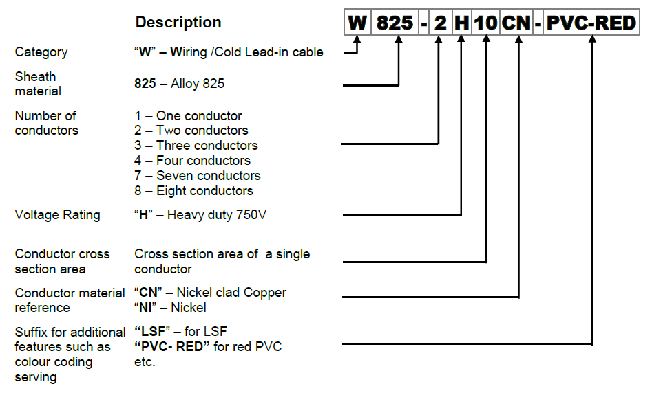
Construction:
Sheath material:
Alloy 825
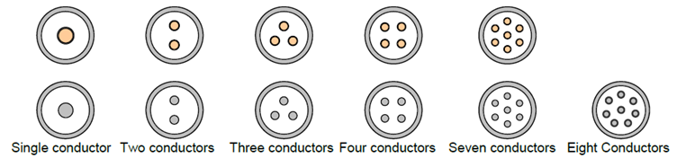
Number of conductors: from 1 up to 8
Conductor material:
Nickel clad Copper, Nickel
Insulation material: Magnesium Oxide (MgO)
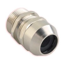
Termination construction
Gland fitting: stainless steel
Potting material: epoxy resin
Tails: standard solid tail length 250 mm
Electrical Parameters:
Supply voltage up to 750Vac (cable)
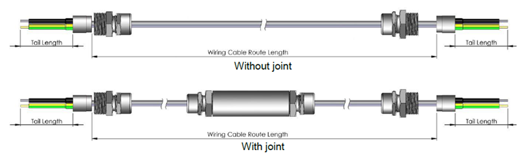
Wiring Cables Termination and Joints
Wiring Cable Metric Range reference
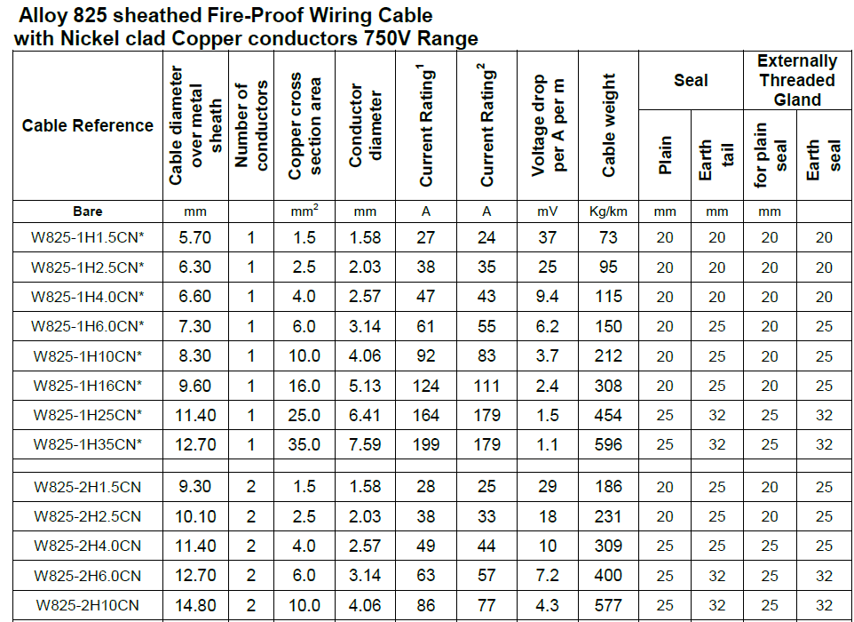
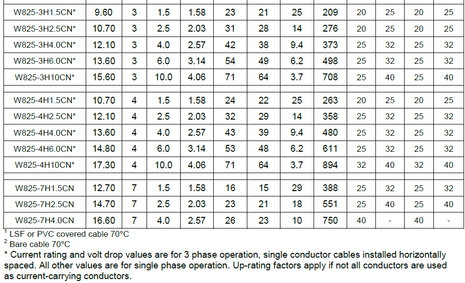
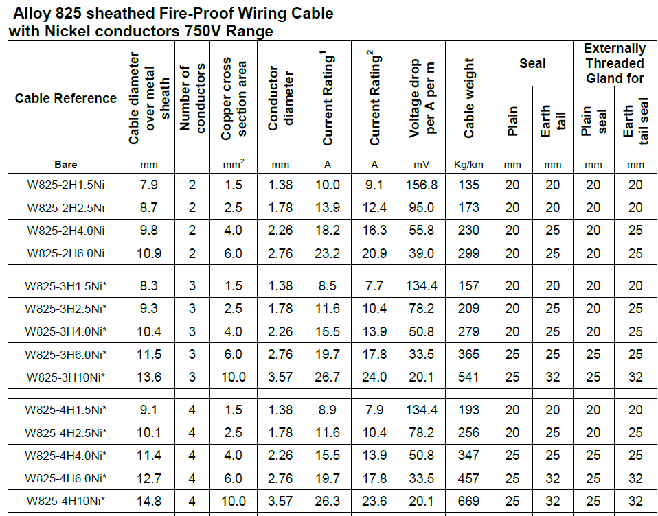
Fire Survival Cable Data Sheet.
The most asked question about MICC/Pyro cable?
How do I install or repair the Cable correctly?
We hope to make it as clear as possible the procedure to install or repair the cable by Mineral Insulated Cable Co., Ltd. the manufactures instructions.
Terminating the Cable.
Preparing the Cable end:
Cut the cable to length required allowing for the appropriate length of conductor tails. Ensure that the cable end is cut off squarely for ease of subsequent stripping. Where PVC sheathed cable is being used the PVC should be cut back prior to stripping the copper sheath.
Mark the point to which the copper sheath is to be stripped back to expose conductors.
Remove sheath, using one of the three methods described below, but ensure that after stripping the cable end is squared off and clean from burrs.
Clean the conductors thoroughly, removing all surplus magnesia.
Once the cable end has been prepared it is important to complete the fitting of a termination as quickly as possible to exclude the entry of moisture and thus obtain a high insulation resistance reading.
Four Methods of Removing Sheath.
 Method 1- Using side-cutting pliers.
Mark the sheath at the point to which the sheath is to be stripped, using the sheath cutter to indent the sheath. Fit the tool to the cable and tighten the wind nut until the cutting wheel is in contact with the with the sheath. Turn the wing nut an additional quarter turn.
 Revolve the sheath cutter around the cable. It is important to note that the sheath must not be cut through but only indented to have a satisfactory clean cut is to be achieved when stripping. Remove the tool.
Using side-cutting pliers, make a small tear in the end of the sheath. The tear is then firmly gripped with the pliers and by twisting the pliers around the sheath it is easily removed in a spiral. Take care on approaching the indent mark to obtain a clean end to the sheath, free from burrs.
Method 2 – Using fork-ended sheath stripper:
Proceed as in method 1 up to the point of making a tear in the sheath with the side cutting pliers.
Fit the fork end of the stripper over the tear and revolve around the sheath until approaching the indentation when the tool should be positioned alongside and parallel to the cable to ensure a clean break on completion of stripping. Should the amount to be stripped exceed the length of shaft on the tool draw it up the spiral and continue with the stripping operation. If necessary, part of the spiral can be cut off with pliers.
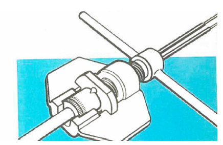
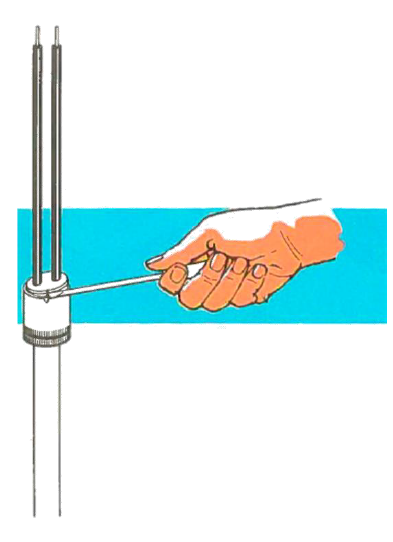
Method 3- Using rotary stripper/ pot wrench tool:
 This compact tool provides the quickest and most efficient means for stripping the cable sheath to fit the popular 1-inch gland. To use the tool, first saw the cable to length and straighten the portion to be stripped. Place gland in tool with back-end gland of gland nut in contact with cutting blade. Set blade by slackening off the wing nut and rotating setting wheel until the cutting edge of the blade in use just clear the thickness of the sheath without fouling the conductors. Tighten wing nut; secure gland by means of the locking screw; insert cable end into gland, apply forward pressure and rotate the handle clockwise.
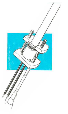
Method 4- Using rotary stripping tool:
This tool is available in 1-inch and 11 -inch only. Place the gland in tool (A) and lock it securely, using spanner. Set cutting blade so that its edge just clears the thickness of the sheath without fouling the conductors; it should protrude just beyond the halfway mark, which can be pencilled on the gland (B). Ensure blade is in pressure contact with gland (C) and tighten holding down bolts. Insert cable end into gland, apply pressure and rotate tool clockwise direction so that the blade engages the sheath.
Space washers for use with new gland assemblies the reduced overall length of the rationalised design of gland necessitates the use of a space washer if the earlier type 1-inch rotary stripping tool is being used.
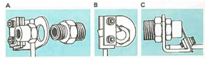
Just clears the thickness of the sheath without fouling the conductors; it should protrude just beyond the halfway mark, which can be pencilled on the gland (B). Ensure blade is in pressure contact with gland (C) and tighten holding bolts. Insert cable end into gland, apply pressure rotate tool in clockwise direction so that the blade engages the sheath.
Space washers for use with new gland assemblies the reduced overall length of the rationalised design of gland necessitates the use of a space washer if the earlier type 1-inch rotary stripping tool is being used.
Fitting the Seal
Before fitting commences you need to check:
- Whether or not a hood or shroud is to be used.
- Whether or not a gland is required
As these should of course be slid on the cable prior to screwing on the pot. If a pot wrench is to be used for screwing on the pot, the gland is put on the cable at the same time as the pot wrench. Check the pot for cleanliness and remove any loose metallic particles.
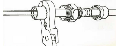 Method 1 – Screwing on the pot grips or pliers:
The pot has self-cutting threads and by pushing the pot squarely on to the cable these can be engaged finger tight. Take a pair of pliers or pipe grips and, gripping the milled shank of the pot, screw the pot down the cable sheath until either the lip of the sheath is level with shoulder inside the pot or alternatively the threads being to bind. If a gland is being employed check from time to time during the screwing operation that the pot can be housed in its normal position in the gland.
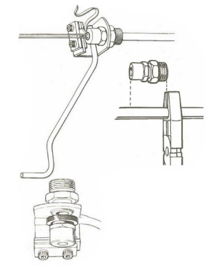
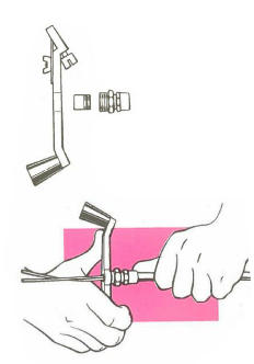
Method 2 – Using pot wrench tool:
This is much quicker, easier, and more positive method of attaching the pot. Because the pot is housed in its normal position in the gland during the screwing operation, this tool ensures that the pot will screw on squarely.
Position the tool, pot and gland as shown. Screw the land into the tool so that the pot is firmly held between them. Push the assembly over the cable sheath, gland first, making sure that the gland compression ring does not foul the cable. Rotated the tool, applying forward pressure, until the pot is properly screwed home. To free the tool simply unscrew the gland.
 Method 3 – Using rotary stripper / pot wrench tool:
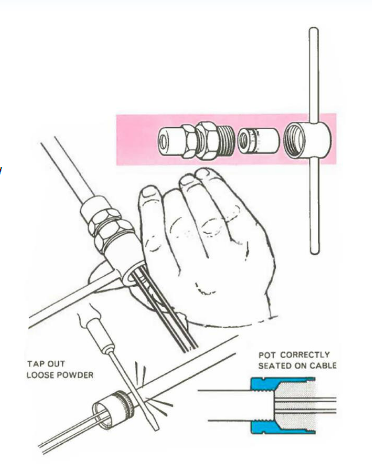
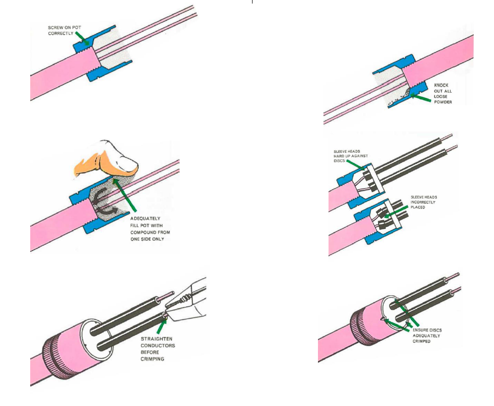
This combination tool has the same features as the pot wrench tool. To use, position the gland, pot and tool as shown. Screw up the gland finger tight. Push the assembly, gland first, over the cable sheath. Applying forward pressure, rotate the tool until the pot is properly screwed home. To free the tool, unscrew the gland. In all cases, after the pot has been screwed on, it is vitally important to remove all loose powder by tapping the sheath or shaking the end of the cable.
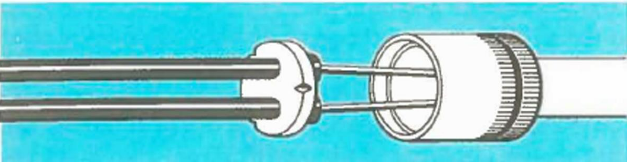
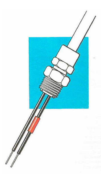
Fitting Discs and Sleeves
Cut the headed sleeves to the required length and thread these through the hole in the disc; pull the moulded head up tightly against the disc. Next, thread the sleeves over the conductors with the moulded heads nearest the pot. Slide the assembly down to the mouth of the pot and check the fit. Position the assembly part wat along the conductors so that the compound can be put into the pot.
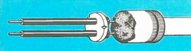
Filling with Compound
Press the compound firmly into the pot from one side only to avoid air pockets forming. Use an adequate amount of compound so that a mound is created beyond the mouth of the pot. Hands should be clean to avoid any extraneous matter being introduced with the compound. Protect any compound that is put aside so that it is kept clean and free from dust etc.
Crimping the Seal
 Press the disc and sleeve assembly down with finger and thumb into the mouth of the pot and remove any surplus compound that oozes out from between disc and pot. There should be sufficient compound to prevent full seating of the disc in the pot with finger pressure- note that crimping tool will achieve this during the final operation.
Always check that the heads of the sleeves have been pulled up tightly behind the disc. To seat and retain the disc in position, the mouth of the pot is crimped at three points around the circumference. Depending upon the material the disc may be notched on the outer edge, these notches being lined up with the crimping pins on the tool. This will ease the crimping operation, although this can, in fact, be done easily at any point on the circumference. Two types of crimping tool are available and are used in the manner described below.
Method 1 – Pyro X Crimp;
 This simple tool will perform up to 100 crimping operations, but immediately any wear on the tool
becomes apparent it should be scrapped. To use the tool, slacken the bolts and thread the conductors through the hole in the top plate, slipping the bottom plate into position below the pot. Screw down each of the bolts a little at a time bringing the crimping pins into contact with the edge of the pot.
When the top plate lies flush with the mouth of the pot the crimping operation is complete. Unscrew the bolts and withdraw the tool.
Method 2 – Pyro Crimp
This excellent tool is simple to use and will give many thousands of effortless crimping operations not only speedily but also accurately. Simple insert the conductors up through the handle of the tool which should be unscrewed so that the pot can be positioned in the nest. On screwing down the handle, the crimping plate is brought swiftly and surely into contact with the pot.
After crimping, the sealing operation is now complete. However, always wipe away and surplus compound that has been forced out of the pot because of the pressure built up during the crimping.
This pressure ensures that the compound has been forced down on to the face of the insulation of the cable as well as up the insulating sleeves. Inspect the seal to see that the disc has been seated properly, that the sleeve has not been pushed down into the pot, and that a satisfactory crimp has been achieved.
This method of making off the seal is the same for the standard of the medium temperature seal.
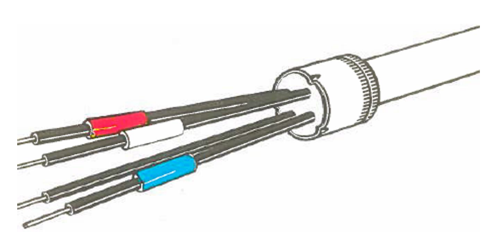
IDENTIFYING CONDUCTORS
Identification of conductors is normally done on completion of the sealing operation. This may be carried out by using PVC extension sleeving, which is available in a range of colours and is a sliding fit over the seal sleeves.
Alternatively, PVC adhesive tape can be supplied either half inch of 5/8 inch width and in eight colours.
We recommend that you make a practice of following the colour combination laid down in IEE Regulations 14th Edition.
TESTING THE INSTALLATION
 The insulation resistance of each length of MI cable may now be tested and as the normal insulation tester is used for this operation it can be combined with the job of identifying conductors, thus dispensing with the often-used bell and battery. An infinity reading on a 500- or 1000-volt instrument should be obtained.
The terminating procedure is now completed, and the cables are ready for connecting.
Where a gland is used this may now be brought into position to house the pot seal and the termination is complete and ready to connect to the box or apparatus.
For a screwed entry, pass the conductors into the box and screw the gland firmly into the box entry. Only after this has been locked into position should the back nut of the gland be tightened to sink the compression ring on to the sheath of the cable.
For a plain hole entry push the gland through the hole and secure inside the box by means of a locknut or locking ring. Again, after connection to the box lock up the back nut of the gland.
The same procedure is adopted for either standard or flameproof type glands but, of course, with an E.S. gland instead of locking up the back nut on the compression ring it is necessary to tighten the two earthing screws on to the sheath. Although reducers and increasers are available and are described in the Accessories Section of this booklet these should rarely be necessary with the MICC standard range of glands with entry threads matching present-day boxes.
CONDUCTOR CONNECTIONS
Section for section a solid conductor (as in an M.1. cable) has a smaller diameter than a conventional stranded conductor. Since M.I. cable also have a higher current carrying capacity than other cables you can at times use a smaller conductor size than is possible with rubber or thermoplastic cables. You might therefore find that the connectors on meters and fuse boards are too large for the M.I. cable conductors. Do not be misled by the mistaken theory that it is then necessary to increase the conductor size by binding it with fine wire and tinning or soldering on a brass ferrule. This procedure is suspect because it may increase the contact resistance. Certainly, where possible double back the conductor, particularly on the smaller sizes, otherwise ensure that the connector screws are bearing directly on the conductor. You should use lugs for conductors of 0·007 square inch and larger where possible.
PARTICULAR TYPES OF INSTALLATION
We have so far dealt with a standard and straightforward job of installing and connecting M.I. cable. We now turn to aspects of installation which may crop up from time to time.
RUNNING LARGE SINGLE CONDUCTOR CABLES
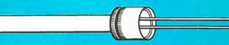
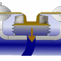
By and large there is no problem about running large single conductor cables, but it is necessary to recognise that sheath losses will occur on a.c. systems in two ways:
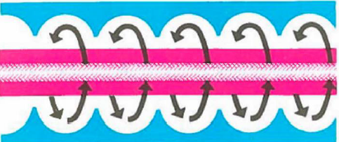
Eddy currents which circulate around the sheath (see illustration above). Circulating currents which travel through the cable sheath in a longitudinal direction (See illustration below).
On a 50 cycle supply the losses from eddy currents are very small and can be ignored. In the case of circulating currents these also may be unimportant, but the following points should be borne in mind.
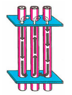
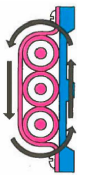
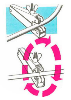
If large single conductor cables are required to pass through ferrous plates at each end, as found in switchgear, bus bar chambers and the like, it may be found that as the cables come under load, these plates will become warm or, in exceptional circumstances, quite hot. This may not create any problem unless they are too hot for the cable terminations or adjacent fittings. If the cables are carrying only moderate currents, say around 100 amps, it will probably be sufficient to overcome the difficulty by simply putting a slot in the plate through the centre line of the cable. If such plates exist at both ends of the run, then both should be slotted. Should the cables be carrying heavy loads and there are dangers of overheating then the ferrous end plates of the switchgear should be replaced with brass or aluminium plates, or alternatively (provided earthing arrangements are satisfactory) insulating plates of Tufnol or teak may be used. When running large single conductor cables, they should not be spaced apart but should be in trefoil formation or certainly in very close proximity to one another. Circulation of air around the cables will obviously be beneficial and this can be improved using standoff or spacer bar saddles, as shown above.
FLAMEPROOF WIRING
Where a flameproof system is required M.I. cables must be a first choice by reason of their fireproof qualities. This system, which has technical and economic advantages, is extensively used for a variety of flameproof applications ranging from small motors to complete industrial flame proof installations.
MICC flameproof glands, which incorporate a longer threaded body, are approved by the Ministry of Power for use with certified enclosures in atmospheres containing Groups II and III gases as defined in B.S.229: 1957.
Straight through joints for flameproof use (see page 128) incorporate a brass sleeve. Two flameproof glands joined by the brass sleeve constitute a flameproof straight joint. Since M.I. cable is itself fireproof, there is obviously no necessity to install it in conduit. The ease of installation resulting from the elimination of heavy conduit makes the work lighter, simpler, quicker, and therefore less costly.
In the event of a fire, it is desirable that the alarm and other circuits should continue to operate, however extreme the conditions, and M.I. cables are of course ideal, as they will continue to operate in temperatures up to l000°C.
Whilst the system of M.I. cable and flameproof terminations is ideal it must be remembered that all other fittings and boxes must also be of the flameproof type and meet the appropriate regulations.
In the case of inductive circuits, it is important to suppress any surges which may be generated.
CONCENTRIC WIRING
Bare or P.V.C. copper sheathed M.I. cables are eminently suitable for use on concentric or earthed concentric wiring systems, both of which utilize the copper sheath of the cable as the return lead.
It will be appreciated that a single-conductor cable can be used in place of the conventional twin, and on three-phase circuits a three-conductor cable would be used to convey a three phase and neutral supply.
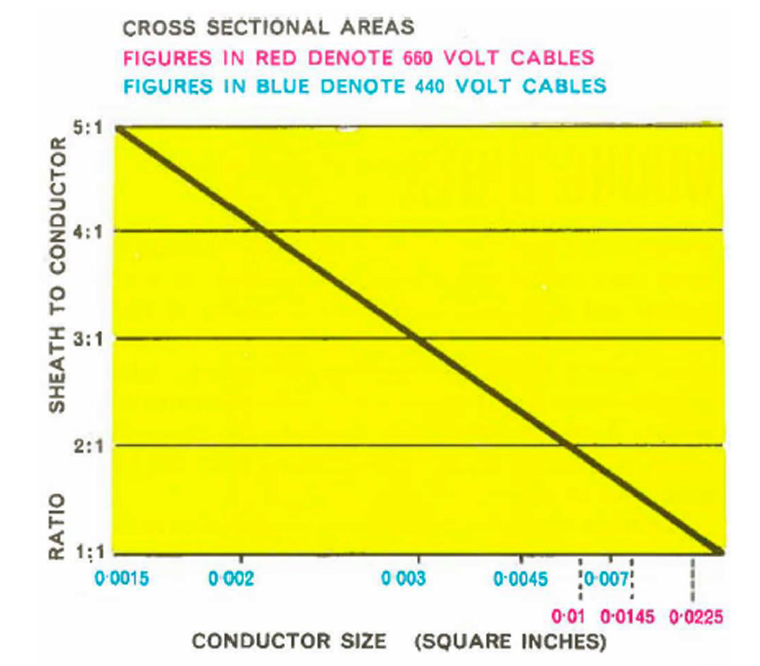
Cost is reduced not only because of the absence of one conductor but also from the reduction in the overall diameter of the cable. Particularly with the smaller cables, the conductivity of the sheath is so high that practically all the voltage drop takes place in the conductor. This means that the length of run for a given voltage drop is considerably higher than that of a corresponding system using two conductors. This applies to a lesser degree to the larger cables, although as the cable size is increased the resistance of the sheath approaches that of the conductor until, at a conductor size of 0·0225 square inch, they are approximately equal (at W°C). This is the size of the largest single-conductor cable that can be used as a concentric cable.
Multi-conductor cables can, however, be used no matter what their size, since in all cases their sheaths are more conductive than anyone conductor.
Regulation number BI24 of the 14th Edition of the I.E.E. Regulations states “At every joint in the external conductor and at terminations, the continuity of that conductor shall be ensured by a bonding conductor additional to the means used for sealing and clamping the external conductor. The resistance of the bonding conductor shall not exceed that specified in Regulation BI22 for the external conductor”.
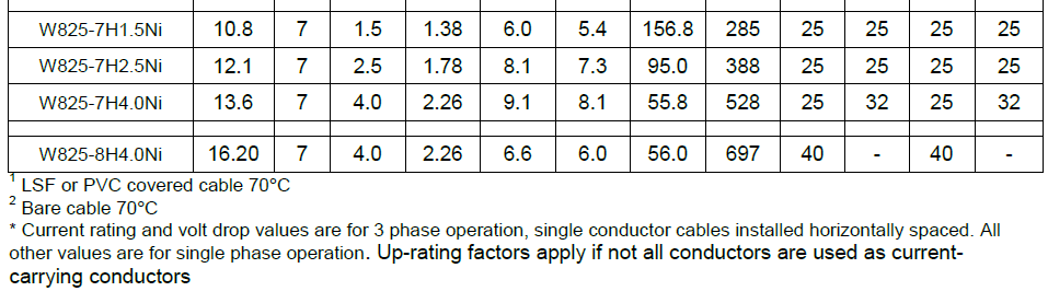
A convenient method of achieving this bonding is to fit the earth-tail type of sealing pot in place of the standard type, when terminating the cable. The ratings for mineral insulated cables used in this way are shown in Table 5. Concentric or earthed concentric wiring systems when used on a public supply network are subject to a few conditions. These special conditions are laid down by the I.E.E. and are covered by Regulations Bl19-B124.
WIRING UNITS
Modern mass production methods, in the building trades, mean that buildings are often constructed on a module system and certain projects such as blocks of flats and offices, schools, hotels and housing estates contain electrical wiring which is repetitive in nature. Similarly, manufacturers of equipment may require repetitive internal wiring. A multi-storey block may contain many flats or offices of identical layout which means power and lighting cable runs of identical length.
For these repetitive installations considerable savings in time, and therefore cost, can be made using prefabricated wiring units. These can be made up in a contractor’s own workshop or supplied direct from the Pyrosales. Details can be taken from plans or elevation drawings and the cables, bare or PVC over sheathed, are cut to exact measurements terminated with seals, glands, and any other accessories such as earth-tail pots. Before dispatch the units are tested to check performance and insulation resistance and both the unit, and the individual conductors can be colour coded for identification. The units can be prepared in kit form and packaged accordingly, so that on arrival on site a complete kit can be placed in each dwelling or suite of rooms. A trial kit is supplied initially and any adjustments in length are corrected for the bulk production. Following this stage, all that must be done when the units arrive is to fit them in position.
This ensures that installation work can be carried out at a fast rate thus avoiding delay to other trades.
The method of fitting the cables naturally depends on the local conditions. Very often the cables may be laid, without further protection, directly on the shuttering prior to the pouring of the concrete floors. This method is used extensively and shows significant savings in installation costs.
The 13-amp ring main circuits may be fitted at a later stage of the contract, and here it is customary to run the cables around the walls either at floor level or at a height of, approximately 15. inches. Subsequently the cables are either plastered over or covered by the floor screed and the small diameters of M.1. Cables are easily accommodated in modern thicknesses of plaster.
Box manufacturers now offer a range of competitively priced boxes. These boxes obviate the need for cable glands, and being of plaster depth, eliminate the expensive cutting of wall surfaces. Any pattern or system of wiring can be accommodated in this manner for all forms of repetitive installation. Apart from building work, prefabricated wiring units are used in many types of machine production as, for instance, petrol pumps which require integral wiring. Obviously, where this system is used there will be a significant saving in time and labour costs and wastage on site will be eliminated. Experience has shown that, compared with a conduit system, a substantial reduction in wiring costs can be achieved by using M.I. cable wiring units.
Extensive use of M.I. cable has resulted from the competitive position of this type of wiring using the standard range and quality of cables.
With the introduction of 250-volt grade cables for domestic installations the cost savings are even more substantial. We have had extensive experience in the use of M.I. cable prefabricated wiring
units in all types of buildings and will gladly advise on current wiring practices, modern trends, fixing methods, new materials, etc.
PROTECTION AGAINST VOLTAGE SURGE
The question of surge voltage has been discussed in the section dealing with cable characteristics. Whenever you consider the hazard of over voltage is likely to arise this can be adequately catered for by fitting our small surge diverters across any offending coil or across the terminals of equipment. Protection against induced surges from indirect Lightning which affects overhead line supplies may be provided by connecting the diverter between conductor and earth at the incoming supply terminals.
These simple and inexpensive devices are a type of nonlinear resistor. The material used has the unusual property of being almost non-conductive at normal (mains) voltage but becoming increasingly and rapidly more conductive as the voltage rises. The surge diverter therefore provides a shunt path for any surge voltage.
The standard diverter is suitable for use on 250 volt and 440-volt circuits. It may be connected across any coil taking up to 120 milliamps R.M.S (160 milliamps D.C.) and operating at a rate of not more than once per second. The steady leakage current is about 0·2 milliamps at 250 volts or 1·5 milliamps at 440 volts.
Do remember to disconnect the diverter when testing the circuit for insulation resistance.
CONSTRUCTIVE SUGGESTIONS
AFTER INSTALLATION
Having just completed the installation you will naturally carry out tests before connecting the supply and the tests will include insulation resistance. Mineral insulated cables are covered by the same regulations and requirements on test values as for other types of cable.
An M.I. cable when sealed has an extremely high insulation resistance value and will therefore meet the most stringent requirements specified in any country of the world and under any climatic conditions.
In the United Kingdom insulation tests are carried out with a 500-volt instrument and with the British climatic conditions no difficulty should arise in achieving an infinity reading. In some parts of the world, where very high humidity values are experienced, the same test figures can be expected on the cable itself but in testing a complete installation due note must be taken of surface moisture on insulators, terminal blocks, and switches which may affect the overall reading.
It should be remembered than an M.I cable must be sealed before testing and that a slight film of moisture across the end face of the cable will be sufficient to give a low reading. Provided the seal is made off in the approved manner this small amount of moisture will be absorbed by the cable and in a very short space of time an infinity reading should be achieved.
If, however you are not satisfied with the I.R. value after sealing then by carrying out the following simple checks you will be able to determine whether the cable has been satisfactorily sealed.
LOW INSULATION RESISTANCE
The most probable reason will be a leaking or breathing seal and provided these are readily accessible you should inspect for looseness of the pot seal or for obvious damage.
If you are not satisfied by a visual inspection, it is possible to apply a simple test to locate a breathing seal.
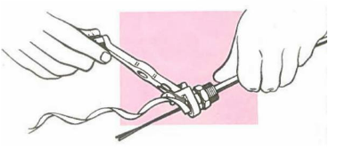
Connect the insulation tester to the cable in the normal manner, and either switch on or turn the handle until a steady reading is obtained. Note the reading. With the tester still operating apply a match or cigarette lighter flame to the cable sheath immediately adjacent to each seal in turn.
The heat need only be applied for a few seconds and if the reading on the tester remains constant then the seal is satisfactory.
If, however, the seal is breathing, moisture will have entered the cable, and the brief application of heat will result in an immediate fall in the reading. This simple test is, of course, quickly, and easily carried out on a surface installation or at a fuse board or distribution board where all the seals are in close proximity.
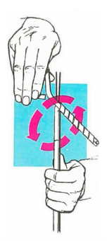
Where the seals are not readily accessible it may be necessary to isolate individual cable runs, and if a naked flame is not permissible (such as in a flameproof area) then the test may be carried out by using alternative sources of heat such as boiling water, a soldering iron, electric heating tongs or even by running a piece of string around the sheath for a couple of turns and pulling backwards and forwards vigorously to provide heat by friction.
Having located a breathing seal, the following procedure should be adopted.
REMAKING A FAULTY SEAL
 Prise out and remove the disc and sleeves and as much of the compound as you can. Next, unscrew the pot and scrape the remaining compound off the face of the insulant. Keep the face of the insulant clean and remember to wipe off the compound with a clean rag.
Alternatively, the seal can be quickly dismantled by using the sheath cutter to cut through the wall of the pot, when the top portion of the pot together with the disc and sleeves can be drawn off.
If the insulation resistance of the cable is very low and the cable is required for immediate service, the damp insulation should be dried out.
Apply the flame of a blowlamp to the cable, about 18 inches from the end of the sheath. Heat the cable to a cherry red, holding the blowlamp steady, then move the flame toward the end of the cable so that the moisture is driven in front of it and out of the cable.
If the reading is reasonable, it is not necessary to dry out the insulation but simply to remove the seal. Clean the cable end and re-seal. Given time a properly sealed M.I cable will, under test, always show an infinity reading as any small amount of absorbed moisture will disperse along the cable and will no longer be of consequence.
AVOIDING FAULTY SEALS
SHEATH DAMAGE
Having checked all the seals and found them satisfactory we must seek other causes for low insulation values and the next step will be to look for damage to the sheath. The test described for locating a breathing seal can equally well be used to locate a penetration of the sheath. Again, moisture has entered the cable and if heat is applied at this point the insulation resistance of the cable will immediately fall.
It may be convenient here to use either a candle or blowlamp and this should be moved slowly along the cable whilst the reading is carefully watched. Immediately any fall in the reading occurs, you will find the sheath has been penetrated at the point reached by the heat source.
REPAIRS TO SHEATH
Having located damage to the sheath it will be necessary to cut and joint unless the damage is of a superficial nature when a repair can be achieved simply by tinning or soldering. If you decide to cut and joint the cable this may be done using either a straight-through conduit box or the straight through joint. The cable is cut at the point of damage, the two ends are stripped as for normal terminating, and this will generally remove both the damaged portion of the sheath and any damp insulation. The ends may then be terminated following the standard procedure.
If such a joint is made in a naturally damp situation such as in a cable buried in the ground, then the connection used can be filled with a bituminous compound or an epoxy resin. When the bituminous compound is poured hot the box should be warmed before filling commences.
How do I connect MICC/Pyro cable to a Soft Skin cable?
Pyrosales have been asked numerous times, “How do I connect MICC/Pyro cable to a Soft Skin cable”. This process is not common, but we had to create a way to assist our customers, so we made a kit that would join the cables together.
Soft–skin flame retardant cables consist of single or multi-stranded conductor cores (copper), individual core insulation (polymer) and an outer insulating sheath (polymer).
Pyrosales call this joining MICC cable to Flex cable (soft Skin), there is a single core join or a multi core join. If you follow the instruction this will enable a join to be completed which maintains the cable circuits integrity under electrical conditions. When ordering the parts, you will require the size of the cable to ensure you receive the correct components.
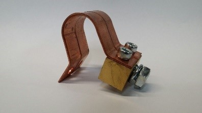 Earth Continuity: When installing an MICC to Flex joint, you need to ensure that you maintain the earth continuity. As the MICC sheath is the earth you will need an Earth Bonding Clamp and organise to terminate a flying cable to the extended Flex cable. Pyrosales carries a full range of earth bonding clamps for this application.
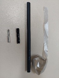 The Single Core kits consist of:
Plated copper Crimp Lug/Link, Glass Mica Tape, Silicone Impregnated Glass Sleeving/Braid, Adhesive lined Thick walled Heatshrink.
The Multi Core Kit consist of the same as the single but with each component multiplied by the core required.
The procedure to connect MICC Cable to Soft Skin Cable:
Step 1: Slide the large heat shrink tube over one of the cables.
Step 2: It is important to ensure then when the final heat shrink is applied it extends 50mm on both ends. The length of cable sheath to remove may be calculated thus:
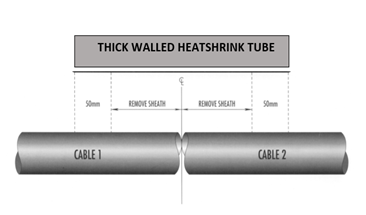
Note: It may be necessary to minimise the diameter of the joint to allow for the application of the final thick-walled heat shrink tube. This can be achieved in a multicore cable by staggering the conductor joints.
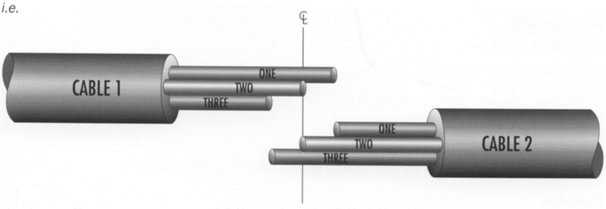
Step 3: Strip the insulation and glass mica tape, half the length of the link, from each core of each cable.
Step 4: Slide one piece of the silicone impregnated glass braid over each of the cores of one cable.
Step 5: Join corresponding cores using the crimp lugs/links provided.
Step 6: Apply the glass mica tape fire barrier. The tape should extend on the insulation by length approximately equal to the link length. The glass mica tape should be applied with the shiny side facing the conductor. Start on the insulated core opposite the silicone sleeve and apply the mica tape with a 50% overlap. Without breaking the tape, continue back across the crimped link finishing on the insulation. Secure the loose end of the tape with a small piece of adhesive tape (not supplied).
Step 8: Slide the glass braid over the glass mica taped cores. Located centrally.
Step 9: Slide the adhesive lined heat shrink tube over the join and locate centrally. Shrink the tubing, starting at the centre and working towards the ends to avoid air entrapment.
Pyrosales supply all accessories and tool for all applications of MICC.

-160x160-state_article-rel-cat.png)


-160x160-state_article-rel-cat.png)

-160x160-state_article-rel-cat.png)


-160x160-state_article-rel-cat.png)


-205x205.jpg)


-205x205.jpg)