If you are using your STS for the purposes of undertaking manually activated no-break transfers during UPS or critical power system distribution maintenance processes then a thyristor only STS is fine.
In case of abrupt failure or steady state degradation a standard thyristors STS will usually achieve a change- over within ¼ of a cycle. In case of manually initiated transfers the break is barely noticeable.
Faster transfers are not achievable using thyristors as there is no mechanism for controlling the thyristor to their off state, (as thyristors have a gate or trigger input for turn on only). There are static power devices capable of gate turn-off (e.g. GTO or IGCT, IGBT etc.), however, due to their complexity are expensive and seldom used. There are also strict limitations and regions of operation for these devices. If these are exceeded then the device is destroyed. Most often these devices limit the capability due to limited current interrupting capacity. As such these devices are seldom used in primary and secondary distribution points.
The i-STS continuously monitors the two incoming supply voltages and the output voltage. If the selected incoming supply source fails or is degraded and the alternate source is available the STS will transparently transfer the critical load to alternate source. With fast digital signal processing a failure is detected within around 150 micro-seconds, and the supply transferred to the alternate supply immediately and transparently. This is achieved without paralleling of the two sources, (true break-before-make) by interrupting the current in the active branch and once the current is at zero connecting the alternative branch. The resultant break to the critical load is not seen no matter how sensitive your critical piece of equipment is. The same can not always be said for a thyristor only STS where a transfer time of 1/4 of a cycle is only able to be achieved. It is known that some equipment is vulnerable to such a break.
The interrupting version of i-STS is suitable for normal operation for currents up to 5 times rated current. These currents can occur in the transient, (e.g. when turning on equipment with high inrush currents such as transformers or equipment with large capacitors inside) and would be considered a normal aspect of operation. All is tolerable even if the currents are greater than this value as long as the source voltage is not degraded. If it is during this inrush cycle some of your critical equipment will be affected unless action is taken. Generally currents inrush of less than 5 times the equipment rating are not considered faults and should be allowed to be supplied through the STS provided the voltages are not degraded. When the current is greater than 6 times a fault may be present; faults greater than the set-point (up to 1200 amperes for 125 Ampere STS), are allowed to pass through the STS without transferring until a circuit breaker else where within the distribution trips. Even if this results in complete loss of supply to our critical load. In this case it would be worse to transfer a fault to the alternate supply and have both supply sources degraded and perhaps lost. To achieve this using the IGBT (which is limited to 6-10) times STS rated current a bypass thyristor is used to shunt the large currents from the IGBT through a parallel connected thyristor instead. Thus great fault capacities are able to be realized. Once the fault has cleared, normal i-STS operation continues.
So why have a current interrupting version? And the answer to that is simple. Minimize the time that the voltage degradation is impressed onto your critical piece of equipment, so that there is no chance of malfunction. In the case where the supplies are not in synchronism or the supplies are at different frequencies an i-STS transfer of the critical load guarantees minimal perturbation to the load and thus no inadvertent or unexplainable tripping of equipment circuit breakers or loss of fuses due to the increased current caused by saturation of magnetics or capacitor inrush. That’s important! Especially where transformers can be saturated by the long break times of thyristor STSs.
The conventional STS approach provides for three (or four in case of 4-pole systems) sets of anti-parallel connected thyristors to form a 3–phase change-over switch. In all cases these switches are designed to conform to the requirements of IEEE Standard 446 susceptibility curve for information technology equipment to allow for uninterrupted load equipment operation. These types of switches undertake a break-before-make transition at current zero. In almost all cases, even during incoming supply failures, these limit the break in the transition to less than ¼ of a cycle.
The i-STSf series of Static Transfer Switches undertake their transfer transition between supplies also as a break-before-make transition except that they use an active current interrupting device to cut-off the current in the conducting phases rather than allowing the current to decay to zero naturally. This approach ensures that the degradation in voltage is limited to 1/10th that may be experienced with the conventional approach.
To provide maximum reliability and ease of system integration; all our large i-STS Static Transfer switches are manufactured without fuses or circuit breakers in the power circuit.
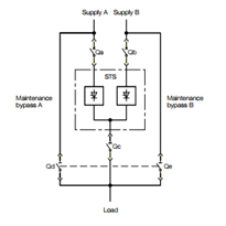
There are a number of topologies available for implementation. Some STSs use forced commutation of thyristors, some utilise various enhancements of the GTO, and some use IGBT technology. They all aim to cut-off the current in the conducting phase as soon as it is established that a transfer is required. Some cut-off the return path current in a transformer utilizing a single device, (break neutral current), While others combine the active switching device in a shared role between the sources. In order to reduce the common point of failure within the STS. Reference is made to accompanying schematics.
In the case of all interrupting STS as soon as a transfer request is processed the IGBT switches off the active current. This occurs at any point in the conduction cycle. The IGBT can cut off the load current in periods measured in micro-seconds. Note that the thyristor around the IGBT plays not role in the transfer process at this point. Once the current has been cut-off the alternate supply thyristors are gated on in conjunction with the IGBT and conduction of power to the load re-commences.
The IGBT is used to switch the active load current. The IGBT is typically rated for 200% of the load current and can typically interrupt peak currents up to 400%.
The bypass thyristor in parallel with the IGBT is only operated under fault conditions. The fault current is carried by the thyristors until the fault is cleared. Note that the load fault is never transferred to the alternate supply source. Load fault sensing is typically set to trigger the bypass thyristor at some 300% hence never subjecting the IGBT to these stresses. The same is applicable for GTO or IGCT topology configurations. They all have limited current interrupting capability.
In case of control or interrupting device failure the bypass thyristor is gated on and the transfer of power is still operable, (not limited to the availability of the interrupting device). In this case a standard thyristor type of transfer will still be able to be achieved utilising the thyristor portions of the switch.
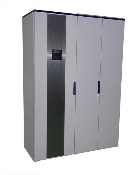
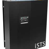
Model Variants
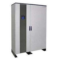
Due to the extra componetry in implementing the interrupting aspect of the STS, the G-Model requires a slightly larger physical implementation.
This has also provided it with additional flexibility and user preference optionallity.
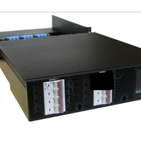
- The Gi-Model has all of its switchgear in a second separate cubicle / enclosure.
- Each of the isolators can also be installed in their own separate enclosure (form 4-type segregation).
- This configuration optionally enables the use of rack-out isolators for additional safety during maintenance and or enhanced isolator repair without ever needing to de-power the load.
- Due to the additional space afforded by the use of the switchgear cubicle cable entry can be either from the bottom or top.
There are no fuses in the Model G and the switchgear utilises non auto isolators. Protection for the thyristors is provided by downstream or upstream discrimination. This simplifies the overall fault discrimination issue effectively eliminating the STS from any fault isolating /interrupting aspect.
The thyristors (standard) are capable of withstanding 35 or optionally 50 kA for 20 msec, (about the time it takes for an upstream or down stream circuit breaker to clear a load fault), upstream settings should ensure that current is limited to this value.
The Maintenance Bypass isolators are mechanically interlocked.
For installation in primary distribution areas where the fault currents may be higher than 30 kA larger fault tolerant devices can be installed.
Back feed protection and thyristor failure protection exists for all phases as per requirements of IEC 62310-1 safety specification for STSs.
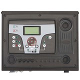
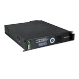
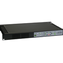
i-STS Static Transfer Switches employ full digital technology, redundant detection and power supply circuitry and all parameters are fully programmable by the user through the front LCD control panel.
Remote monitoring of each STS is available via Ethernet LAN on any PC on the network, Modbus TCP, Modbus RTU or SNMP.
All i-STS units are manufactured to meet the relevant Australian Standards and conform to IEC 62310-1, 2 & 3 STS safety specification requirements.


-205x205.jpg)