The signal cables that are bundled together or laid close to each other in a wire trough, even for short distances that the frequencies of the oscillator in the individual signal conditioner driving the excitation signal to each LVDT vary slightly.
Since the signal cables are close together, they can capacitively couple among each other, resulting in a very low frequency signal that is the difference between the frequencies of the individual oscillators. This difference frequency signal can ride on the DC output of the LVDT signal conditioners, appearing as low frequency ripple or noise with a period measured in fractions of a second, or as a repetitive slow drift with a period of many seconds. When a pair of LVDTs is used together for redundancy, this effect may be evident on only one channel of the system. In systems with larger numbers of LVDT channels, this effect may be found in one or more channels, depending on many factors like cable length and layout as well as shielding and grounding.
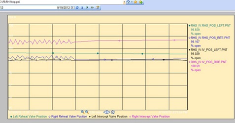
The chart below show an example of this drifting over time on the left side and the elimination of the effect utilising the Master /Slave function
The waveform above in the output was noted in right reheat and intercept valve positioners that was using dual LVDTs in redundant systems. The master / slave function removed the beat frequency signal and the waveform flattened.
The typical way of solving this problem in multiple channel systems is to create a "master" oscillator by using the oscillator from one of the signal conditioners to supply the same excitation frequency to all of the LVDTs. The oscillators in the other LVDT signal conditioners are overridden by the master and considered "slaves". The idea is that there cannot be any beat frequency interference if all the LVDTs are operating at the exact same frequency.
This practice works quite well but has a major drawback, because the "redundant" system is no longer fully redundant. The system is now dependent on one oscillator in one signal conditioner to supply all the LVDTs with the proper excitation frequency. If the master fails, two things could happen: either your other channels stop operating, or they revert back to their original oscillator frequencies and the multiple channel DC outputs now display beat- frequency-produced noise, ripple, or output drifting. Many companies offer LVDT signal conditioners with a master/slave function, but they all are fully susceptible to the beat frequency problem if the designated master oscillator falters or fails. Sometimes when LVDTs are used in a redundant pair this will be evident on only one channel of the system. In multiple channels it can cause similar effects in one or multiple channels or none and depends on many factors like cable layout, grounding, shielding along with various cable lengths etc.
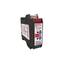
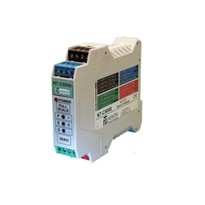
S1A signal conditioner from Bestech Australia manufactured by Alliance Sensors has solved this beating problem as its variants have a digital address for RS485 communication capability, and it uses this digital feature to maintain the full redundancy of multiple LVDT systems. If the "master" were to fail, another "master" having a different digital address would instantly come on stream to maintain a single excitation frequency. In this approach the only thing lost in a "master" oscillator failure is the former master channel itself. For multiple channel LVDT systems, the integrity of the output signals from the other channels is fully maintained. This "auto-mastering" feature is unique to the S1A and its variants.
For more information on S1A please contact Bestech Australia.