

The information below will instruct you on how to automatically fill the water tank directly from the bore or well.
The bore pump starts when the water level drops in the tank and the pump stops when the tank is full.
Automatic monitoring of the water level in the tank so that the pump starts when the water level is low and the pump stops when the tank is full.
NOTE: The info below is relevent to our Franklin Electric bore pumps, motors and controls.
A – A float Switch in the tank can monitor the water level.
If using a 3 Phase bore pump, one or two float switches can be wired into the ‘CP3 Control Panel’. The CP3 Control Panel is for 3 Phase bore pumps from 0.37kw to 7.5kw motors with DOL starters. The CP3 option needed to perform this function is ‘Option BLC’ which is the relay to suit 1 or 2 float switches. You will also need to purchase the ‘float switch’. The float switches are available in different lengths from 1m to 50m. For this set up you will need the following:
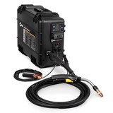
- CP3 Control Panel. These are available in different sizes depending on the kw of the submersible motor. They range from 0.37kw up to 7.5kw.
- Option BLC. This option is for the relay which goes into the CP3 Control Panel.
- Float switch. The purpose of a float switch is to open or close a circuit as the level of water in the tank rises or falls.
Alternatively, you can use the ‘Level Control Panel’ with the ‘LLR option’. The Level Control Panel has the added feature of ‘Overload Indication’ and ‘Low Bore Indication with Reset Button Indication’.
The Level Control Panel can also be used for 1 Phase bore pumps as well as for 3 Phase bore pumps. For the ‘Level Control Panel’ setup you will need the following:
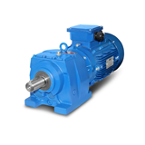
- Level Control Panel. These are available in different sizes depending on the kw of the submersible motor. They range from 0.37kw to 3.7kw for a single 1 Phase 2-wire motor, from 0.75 to 3.7kw for a 3-wire single 1 Phase motor and from 0.75 to 7.5kw for a three 3 Phase motor.
- LLR Option. This option is fitted into the Level Control Panel and is for the ‘Start on level fall, Stop on level rise for tank filling.’
- Float Switch. The purpose of a float switch is to open or close a circuit as the level of water in the tank rises or falls.
B – ‘Water Level Probes’ can be installed in the tank to monitor the water level.
If using a 3 Phase bore pump, the probes can be wired into the CP3 Control Panel. The CP3 Control Panel is for 3 Phase bore pumps from 0.37kw to 7.5kw motors with DOL starters. The CP3 option needed to perform this function is Option BLC which is the Probe relay to suit 1 or 2 probes. You will also need to purchase the probes. The probes are available in different lengths from 20m to 200m. For this set up you will need the following:
- CP3 Control Panel. These are available in different sizes depending on the kw of the submersible motor. They range from 0.37kw up to 7.5kw.
- Option BLC. This option is for the probe relay which goes into the CP3 Control Panel.
- Water Level Probes detect the level of water in the tank or bore.
Alternatively, you can use the ‘Level Control Panel’ with the ‘LLR option’. The Level Control Panel has the added feature of overload indication and low bore indication with reset button indication. The Level Control Panel can also be used for 1 Phase bore pumps as well as 3 Phase. For the ‘Level Control Panel ‘setup you will need the following:
- Level Control Panel. These are available in different sizes depending on the kw of the submersible motor. They range from 0.37kw to 3.7kw for a single 1 Phase 2-wire motor, from 0.75 to 3.7kw for a 3-wire single 1 Phase motor and from 0.75 to 7.5kw for a three 3 Phase motor.
- LLR Option. This option is fitted into the Level Control Panel and is for the “Start on level fall, Stop on level rise for tank filling.”
- Water Level Probes detect the level of water in the tank or bore.
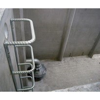
C – A Double Ball Float in the water tank
For this system to operate efficiently, you would need a pressure switch (such as the Telemecanique pressure switch) and a pressure tank. The pressure switch is wired into the pumps starter/control box circuitry. The double ball float in the tank works on pressure. When the tank empties, the float releases the pressure in the line which indicates to the pressure switch to turn the pump on. For the ‘Double Ball Float’ setup you will need the following:
- Telemecanique Pressure Switches are for controlling water pressure booster sets in conjunction with an expansion vessel. They have adjustable cut out and differential (cut in) pressure to suit your application.
- The pressure tank absorbs water pressure by utilizing pre-charge compressed air / bladder arrangement. Because of this stored pressure (energy), when a valve or tap is opened water is pushed out of the tank through the plumbing system. When the water in the pressures tank drops below the pre-charged value, the pressure switch is activated turning on the pump. The pump then refills the pressure tank. The combination of the pressure tank, pressure switch and the pump is what allows water to flow through your home or garden.