Recommended Usage.
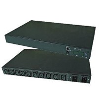
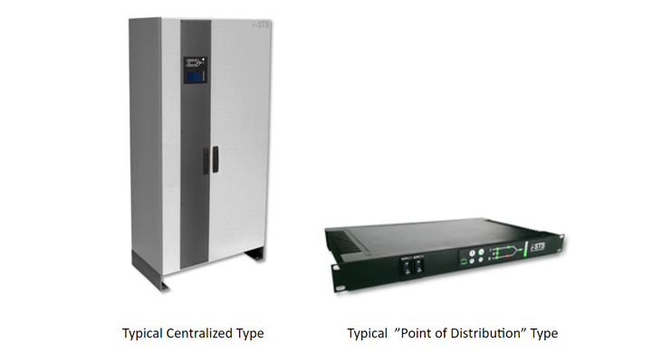
There are basically 2 types of STSs, centralized (larger capacity that are placed within the power distribution system) and “point of distribution”, those that are placed close to the load. The latter are generally rack mounted units rated less than 100 Amperes. Why is this important? It’s important because you don’t want to use a “point of distribution” type STS where there are large fault currents, next to or within the primary power distribution system. That’s because these units are designed to be placed close to the loads not close to the sources. If there was to be a fault when they are placed within the distribution system they may not be able to break the fault current and this could cause generation of arch flash and fire. The i-STS range of “point of distribution type” Static Transfer switches are safe for installations up to 20,000 Amperes. They have special reinforcement and fuses to limit the fault current and protect up to this level.
Fuses VS Circuit Breakers VS Source Only Protection Systems.
Low capacity ATS or STSs may use onboard circuit breakers to break a fault. Most small circuit breakers have only a 1 to 6 kA interrupting capacity. If the fault current is greater than what the circuit breaker can clear, the fault may not be cleared and the unit could catch on fire.
Some ATS/ STS do not have any incoming protection at all (no circuit breakers or fuses) and in these cases the power sources are protected by external switchboard breakers. These may be of the miniature (17.5 mm width & 6kA) and are described by A, B, C & D curve responses.
Most commonly, circuit breakers with C or D curves are installed, however all of these circuit breakers are relatively slow. This means the fault current can exist for a period of time that exceeds that of the devices / STSs capability to survive. Alternatively in some cases the lead lengths and cable size is so small that the fault current may be less than the breakers operating limit, again causing the fault to exist for a longer and longer time. This condition will continue until something clears the fault, which might end up being the failure of internal wires or a weak point within the STS/ATS. It is therefore advantageous to always ensure that the installed STS/ATS is made safe from within.
All i-STS “point of distribution type” Static Transfer Switches are reinforced and have large fuses installed, typically 100 Amps, that will ensure that for all faults the STS will fail safely. The fuses are 3 to 6 times the rated operating value of the load so these STS can cope with large overloads. The overload capacity of fused i-STS devices are 400 Amperes for 1 second, 100 Amps for 30 seconds and 2000 Amps for 1 cycle and 20,000 Amps for less than 1 milli-sec. These assure safe operation and protection.
Operational Temperature
Many ATS/STS are advertised as being rated for 16, 25 or 30 Amperes but often have a caveat, for example: “Under the condition of 25 ?; if the environment temperature is over this the, the product should be de-rated to 25A. etc.” All electronic equipment operate most reliably at ideal temperatures of 25oC, and while i-STS devices are no different, they can operate reliably between 40oC - 55oC without de-rating. Above the upper temperature threshold, i-STS devices will not fail, although the overall long term reliability may be affected. Other transfer switches may behave erratically or fail catastrophically. All i-STS Static Transfer Switches are qualified to operate at 55oC with their full rated load.
Voltage Rating
Many retailers will provide transfer switches with generic voltages of 120 or 230 V only. When specifying your ATS/STS ensure that it is functionally insensitive to voltage distortions of 10 to 15%. If the device is operated with voltages distortions beyond its capability, the operation may become problematic and it may begin to continually transfer between the sources or randomly transfer without cause or explanation.
This could also happen if for example an ATS/STS rated to 230 V with ±10% allowable voltage tolerance is connected to a 240 VA supply, and the voltage is slightly higher than expected by 5 to 6%. Similarly if an ATS/STS rated to 120 V is installed into a 115 V system but the source voltage is actually 110 V, then its operation may again become erratic. Ideally a UPS will output a near perfect sine wave, however by the time it reaches the connected equipment, factors such as cable impedances and non linear load current caused by long cable runs will often cause the voltages to be distorted. Some ATS/STS have not been designed to factor in the nominal operating voltage and its distortion because their primary function is to protect the critical loads from complete supply failures only and perhaps not bad power. All i-STS static transfer switches monitor voltage to protect the load against steady state surges and sags and have at least ±15%, many in excess of ±20% voltage tolerance. Additionally, the i-STS control system allows for the transient state voltage parameters to be adjusted, so the load will stay connected through deviations from the nominal voltages. In addition the allowable voltage distortion can be up to 15% without mel operation.
Frequency
If you purchase an ATS/STS from a different continent, it may not compatible with your supply source frequency. 50 Hz rated STSs may not function correctly at 60 Hz and similarly 60 Hz units may not function correctly at 50 Hz. All i-STSs will operate at both 50 Hz or 60 Hz and will auto-detect the source frequency.
Transfer Type
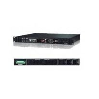
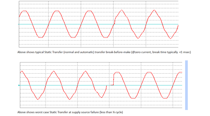
In a previously article, I wrote about ATS, STS and hybrid types of transfer systems. Only a true “Solid State Static Transfer Switch”, such as i-STS devices, will guarantee a quick changeover at a point in the AC wave where there is no power flow to the load.
Mechanical relay based transfer switches will perform changeovers at any point in the waveform. Potentially this can occur at the peak of the waveform, which is the worst possible time. This matters because the peak of the waveform is the point of maximum energy transfer, either voltage or current, and transferring at this time can causes voltage contact arcing. It also generates the maximum radiated interference and over voltage spike and you may need to consider whether your connected equipment is sensitive and needs to protected against this.
Most ATS/STS use break-before-make transfers which means the sources do not overlap. Ideally, the break time should be as small as possible. Relay and hybrid type transfer switches which rely on electromechanical relays to open prior to undertaking the transfer and have transfer times between ½ cycle and up to 2 cycles depending on the sensing and relay electromechanical operating times. For some connected equipment, this break time is too long. Typically with i-STS devices the break time (or transfer time) is as little as 1 msec (one twentieth of a cycle) and in worst case up to ¼ cycle because. In i-STS devices, the switching performed by solid state semiconductors (Thyristor or SCR) which are fastest and most predictable and rugged preferred transfer mechanism.
Overrating of Power Paths
Manufacturers of ATS/STS & Hybrid type equipments may save on costs by using componentry which has limited power handling capability. This severely limits the ability of their devices to cope with downstream equipment faults, and the result is that small relays weld together or blow apart, or the underrated hybrid type SCRs fail. i-STS devices, including the smaller “point of Distribution” types, are generously overrated and can supply load faults in excess of 2000 Amperes for 1 cycle without damage to the semiconductor switching components. Typically, the SCRs/Thyristors are rated to 200% - 500% of the steady state operational rating. In addition, the semiconductors are impervious to wear and tear and can switch the load millions of times if needed without fail. It is also necessary that the cables and conductors inside the STS are equally suitable and reinforced to cater for these large overcurrent demands without degradation and without failure.
Asynchronous Operation
The best case scenario to transfer a load between two supplies is to have both supplies in synchronism, meaning they are both of the same frequency and phase. In practice, it might not be possible to maintain synchronism of both sources. Some ATS/STS and hybrid systems don’t consider synchronism at all and transfer in any case. This can be detrimental to the load as it can cause large inrush currents which can damage to some critical load equipment. Where possible for both manually and automatically initiated transfers on i-STS devices, the system will wait until both sources are synchronised before transferring.
If feeding transformers or inductors, solenoids or motors on i-STS Static Transfer Switches the user can select to set the transfer to optimize the change-over (VT proportional algorithm) so to optimize the point of switchover to minimize these currents and the break times will always be shorter than the inferior ATS/STS & hybrid types.
UPS Ecomode Compatibility
Many UPS operate in a line interactive mode or off-line, or Ecomode. The inverter is operating at no load (most efficient), and the critical load is powered from the bypass and when necessary switches from bypass mode to on-line mode when required. The transition unfortunately is not seamless and up to ½ cycle could be lost in the transition from on-line and off-line modes. i-STS devices have a special mode that will not switch-over to the alternate source when this break occurs while the UPS is coming on-line. In the case where the transition is longer than allowed for by the critical load, the i-STS will transfer to the alternate standby source. Transfer switches that do not have UPS Ecomode compatibility could behave unpredictably as they may detect the break and other times they may miss it, while the i-STS system has full digital sampling systems that can reliably detect this occurrence and properly protect your load.
Load Fault Sensing
From time to time the critical equipment connected to the ATS/STS may develop a fault that causes the load current will rise to a level which maybe hundreds or thousands Amperes, and also affects the voltages. The degree to which the voltage will be affected is a function of the stiffness in the source. A UPS has a very limited capacity to provide fault currents and its voltage will be quickly affected. An inferior ATS/STS will detect this voltage disturbance and transfer the fault to the alternate source, thereby potentially affecting both sources. This can be disastrous because because it could affect all connected equipment, therefore it is imperative that a good STS does not transfer the load fault to the alternate source. i-STSs have fast fault detectors and will inhibit a transfer and optionally isolate the load item and report the load fault occurrence on the display.
MTBF/ MTTR (Mean Time Between Failures/Mean Time to Repair)
For i-STS devices, the MTBF is 1 million hours which is in excess of 100 years. This figure is a calculated value based on MIL-217E calculation, manufactures FIT data and based on actual statistical monitoring of total equipments and equipment performance for the past 16 years. This has been achieved through the design and engineering of rugged circuitry with inbuilt redundancy, quality controls and correctly specified and sourced componentry.
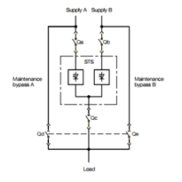
Most manufacturers of ATS/STS don’t consider MTTR, however, if the inevitable servicing or replacement of parts comes about in your lifetime, you will want the ability to remove and replace the power module without costly shutdowns. Nearly all of the i-STS models have a maintenance bypass, some featuring a hot-socket field replaceable power modules which can be replaced transparently and without interruption to your load in seconds.