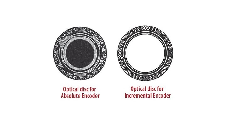
Since the absolute encoder needs to encode a unique value for the shaft position, the number of tracks on the disc and corresponding phototransistors depend on the resolution sought and number of bits used.
For example, for a 12 bit absolute encoder with resolution of 4096, you need 12 tracks on the disc. Depending upon the shaft position, the phototransistor output is modulated in a gray-code pattern, which can be converted internally to binary or BCD.
The size, complexity and cost of absolute optical encoders increases exponentially with resolution, as the pattern gets increasingly complex with increased number of bits.
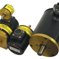
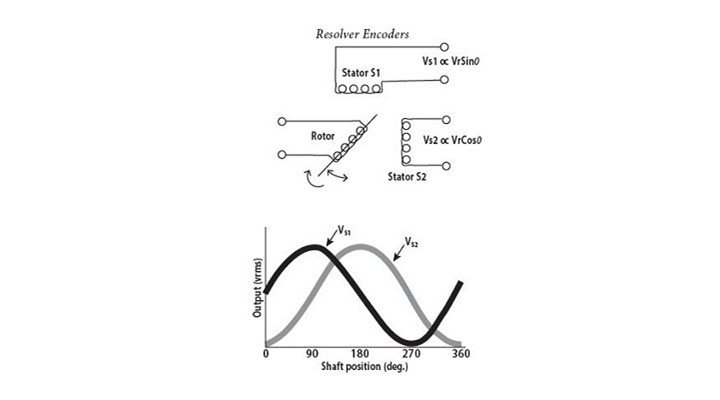
Resolver Encoders
Resolvers, invented during World War II for military applications are by far the most rugged position transducers available.
Resolver is essentially a rotary transformer, having one rotor winding and two stator windings. The stator windings are located 90° apart. Either rotor or stator winding can be used as primary. Typically, the rotor winding is driven by a reference voltage at a frequency ranging from 400 Hz to several KHz.
As the shaft rotates, the output voltages of the stator windings vary as the sine and cosine of the shaft angle.
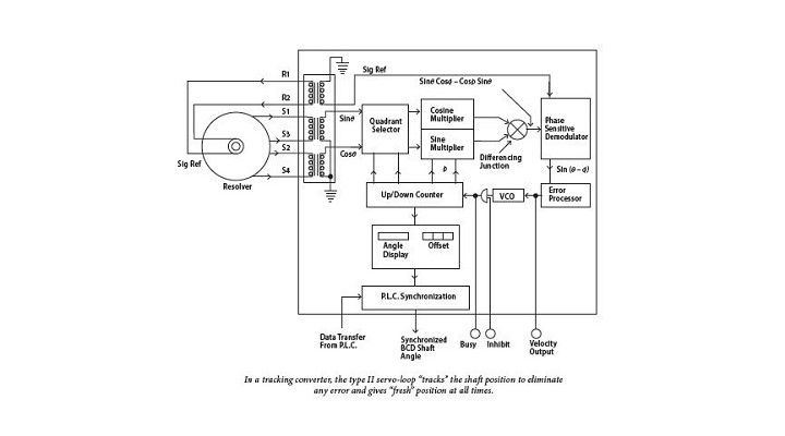
Ratiometric Tracking Converter
(A typical block diagram for a Ratiometric TrackingConverter is shown in figure 3.)
The circuit features a Type II servo-loop that comprises of sine/cosine multiplier and an error amplifier together with phase sensitive demodulator, error processor, voltage controlled oscillator(VCO) and an up/down counter.
Since the VCO is controlled by an error integrator, the greater the lag between the actual shaft angle and the digital angle in the counter, faster will the counter be called upon to "catch-up" or "track" and eliminate the error. The information produced by this type of converter is always "fresh", being continually updated and always available at the output.
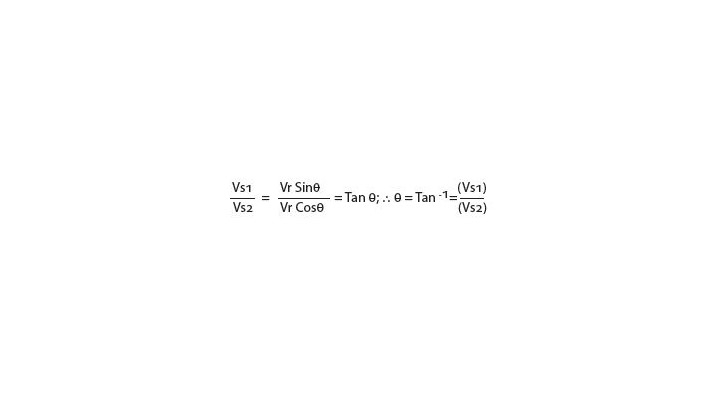
As an added bonus, additional outputs — such as an analogue output proportional to the shaft RPM to eliminate external tachometers and a busy signal pulse for incremental pulse applications — are also available. The basis of determining the shaft angle in a ratiometric converter is the ratio between the two stator signals.
From this relationship it can be noted that the angle is no longer a function of the induced rotor voltage Vr, but rather the ratio of VS1 and VS2. Therefore, variations in the rotor voltage Vr, frequency and temperature are no longer factors in a ratiometric converter. This results in a highly accurate and repeatable resolver-to-digital converter.
Resolver encoders from Autotech are available both as Incremental as well as Absolute outputs.