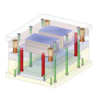
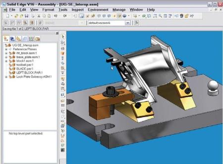
Solid Edge powerful assembly design tools are used to build components around the NX part – using unique systems design capabilities to ensure accurate fit and function of the welding fixture before any parts are manufactured.
Solid Edge provides users with the ability to access the NX part without any translation. As a result, tooling work can be carried out in parallel with product design and part notification for updates to all team members; and the fixture can be changed accordingly without having to start from scratch.
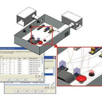
Using Solid Edge helps you recognise and work with NX parts and assemblies, automatically generating the correct data, even though both types of file have the same extension (.PRT) in NX. Both solid and sheet bodies can be utilised, even when a file contains multiple solid bodies, and the NX designer can define which geometry will be transferred to Solid Edge.
For NX assemblies, Solid Edge will recreate the assembly structure – occurrence names, colours, file names – even when the original assembly files do not reside in the same folder. The level of interoperability is such that Solid Edge can find the NX part files related to a given assembly and recreate an accurate view of the assembly.
The NX files present in the Solid Edge assembly will remain associative back to the NX application, and can still be opened and worked on. If the original part is modified, Solid Edge will clearly show that the geometry is out-of-date with respect to the original, and the user can update as necessary. This can be either a manual or automatic process.
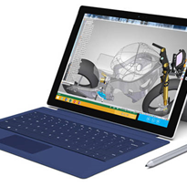
Because synchronous technology works directly on 3D geometry you are able to use Solid Edge with synchronous technology edit 3D files that were originally designed in NX.
Delphi Corp. uses Solid Edge to open 3D product geometry
Manufacturing engineers at Delphi Corp. Energy and Chassis Systems Division use Solid Edge to open 3D product geometry (NX models) directly into their CAD software. They either access the product data directly using Delphi’s corporate product lifecycle management (PLM) system, based on Teamcenter Engineering or have it sent via the Delphi network from the product designers.
Opening product geometry directly is 50 to 80 percent faster than the previous method that required data translation from 3D to 2D.
It is also highly accurate because the product designer's model data is used directly in Solid Edge. Because the previously non-associative 2D tool designs are now associative in Solid Edge, similar savings occur each time there is a product change that results in a tool change.
In addition to using NX product data into Solid Edge, machine designers can directly incorporate NX machine models and assemblies into their Solid Edge assembly. This makes it possible to utilize data from those suppliers that use NX for machine design.
- Suppliers
- New to IndustrySearch? Book a Demo
- Advertise with us
- Login
- Email Marketing
- Buyers
- Get Quotes
- Articles & Ideas
- Login
- Subscribe to newsletter
- My Details
- Get Quotes
- Automation & Control
- Automotive Workshop Equipment
- Commercial Cleaning Equipment & Supplies
- Construction Equipment & Heavy Machinery
- Conveyor Systems & Components
- Electrical & Power Generation Equipment
- Electronic Components
- Farming & Agriculture
- Food & Beverage Processing
- Forklifts & Forklift Attachments
- Hydraulic & Pneumatic Equipment
- Industrial Materials, Tools & Components
- Industrial Pumps
- IT Hardware & Industrial Computing
- IT Software & Applications
- Laboratory Equipment & Instruments
- Manufacturing & Industrial Equipment
- Material Handling & Lifting Equipment
- Metalworking & Machining
- Mining Equipment & Machinery
- Packaging & Labelling Machinery
- Pallet Handling Equipment
- Personal Protective Equipment
- Security & Surveillance
- Test & Measurement
- Transport & Logistic Equipment
- Warehouse Storage, Shelving & Racking
- Waste Treatment & Environmental Management
- Welding Machines & Accessories
- Woodworking & Joinery Machines
- Workplace Equipment
- Workplace Safety Equipment
Trusted by 1,000,000+ Australian industrial buyers
Buyers
- Discover products & solutions
- Login
- Subscribe To Newsletter
- Browse All Products
- Read Articles
Suppliers
Advertise
- Promote your products & solutions
- New to IndustrySearch? Book a Demo
- Login / Forgot Password
- Advertise Your Products
- Success Stories
- Email Marketing
- Suppliers
- Advertise with us
- Login
- Email Marketing
- Buyers
- Get Quotes
- Articles & Ideas
- Login
- Subscribe to newsletter
- My Details
Get Quotes
- Automation & Control
- Automotive Workshop Equipment
- Commercial Cleaning Equipment & Supplies
- Construction Equipment & Heavy Machinery
- Conveyor Systems & Components
- Electrical & Power Generation Equipment
- Electronic Components
- Farming & Agriculture
- Food & Beverage Processing
- Forklifts & Forklift Attachments
- Hydraulic & Pneumatic Equipment
- Industrial Materials, Tools & Components
- Industrial Pumps
- IT Hardware & Industrial Computing
- IT Software & Applications
- Laboratory Equipment & Instruments
- Manufacturing & Industrial Equipment
- Material Handling & Lifting Equipment
- Metalworking & Machining
- Mining Equipment & Machinery
- Packaging & Labelling Machinery
- Pallet Handling Equipment
- Personal Protective Equipment
- Security & Surveillance
- Test & Measurement
- Transport & Logistic Equipment
- Warehouse Storage, Shelving & Racking
- Waste Treatment & Environmental Management
- Welding Machines & Accessories
- Woodworking & Joinery Machines
- Workplace Equipment
- Workplace Safety Equipment
Trusted by 1,000,000+ Australian industrial buyers