With guaranteed up times now days, a 10 per cent chance of a power outage is just not tolerable.
As we add in batteries, connections, generators, supply distribution and maintenance our overall system looks very vulnerable indeed.
Redundant parallel operated UPS configurations also flounder in their attempt to increase reliability estimations marginally above 200,000 Hrs. A far cry from the 1,500,000 Hrs that these configurations derive from theoretical calculation.
This inability to achieve theoretical values is usually because of equipment and distribution interdependences. i.e. They are not truly independent and a failure of one item tends to cause failure of the system as a whole.
Dual- and tri-chord distribution systems were developed to remove these interdependences, however, not all computer room equipment has dual / tri chord technology implementations and occasionally for those that do; the systems often cannot survive with one source removed.
Static Transfer Switches, (STS) provide a convenient and effective way of addressing the loss of a supply by transferring the critical load to an alternate power source. A good switch will do this transparently to the load irrespective of the nature of the degradation or fault on the supply side. As long as there is a healthy supply the STS will maintain critical power to your systems.
Because STSs are not as complex as UPS equipments, operate independently and are close to the point of power usage reliabilities of 1,500,000 Hrs are realisable. That’s an availability of 99.4 per cent or 0.65 per cent chance of unavailability. There are basically two schemes to consider.
Centralised and de-centralised distribution
In the centralised system large capacity Static Transfer Switches take the power from two UPSs and a single feed is distributed to the critical loads which may be on different floors within a multi story building. Sometimes two UPSs and 2 Static Transfer Switches are employed to deliver 2 feeders throughout the building thus improving additional security dual cord distribution.
The key features to a centralised critical power distribution scheme are outlined below.
To dual equipment with dual cord power supplies
In these larger distribution systems single cord equipment is also supplied but not protected against distribution / switching failures down stream of the equipments. These equipments are typically rated from 100 – 1250 Amperes and need to be capable of withstanding large fault currents because they are usually placed in, near or adjacent to the electrical power reticulation infrastructure.
Other schemes distribute the main feeders of the two UPSs up the building close to the critical loads and then use Point of Distribution Static Transfer Switches in 19 inch rack systems to supply critical non dual cord equipment power. This provides the single cord equipment with almost the same reliability as the dual cord equipment topology, (see diagram overleaf).
In a de-centralised (Point of Distribution system) the critical loads are protected right up to the critical piece of equipment. The Equipment is much smaller in rating because the power density in the rack is limited but typically these Static Transfer Switches are rated from 10 – 63 Amperes and can be either single phase single or double pole or three phase 3 or 4 pole. Because the Static Transfer Switches are so efficient (99.8 per cent) there is almost no heat contribution, take up only 1 RU (44mm) of space and generally provide greater overall system reliability because you’re not putting all your eggs in one basket, (e.g. can build in redundant operating systems and load distributions so that a failure of one aspect of the distribution system doesn’t cause failure of the mission critical IT infrastructure as a whole.
The larger centralised schemes generally and mostly always employ Thyristor or SCR based Static Transfer Switches. These are very reliable and very rugged.
In smaller de-centralised systems or point of distribution type utilisations sometimes non static (thyristor or SCR) based switches are used because they are cheaper. These often utilise fast switching electromechanical switching devices. These have breaks in excess of ¼ of a cycle, sometimes approaching a whole cycle under loss or low supply conditions. Much equipment may ride though this period, however, some won’t and the more expensive and critical the equipment becomes the more critical to short power interruptions it appears to be.
Further if a load fault occurs the STS must not transfer the fault to the alternative source and must be cleared by the original source, contactors used in these STSs do not have the fault capacity to survive such a condition causing either loss of power to the critical load and or the inadvertent paralleling of the sources because the contacts have welded together, either way there a throw away item.
So what is the alternative technology?
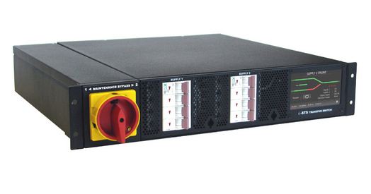
1RU Static Point of Distribution Transfer Switches are available and address all of the shortfalls of their electromechanical counterparts. To achieve effective no-break supply transfers solid state switches are necessary. Typically these contain thyristors which are robust and have a very high load fault tolerance.
These are found to be suitable but for the most critical of equipments. The only disadvantage of thyristor only STSs is that they switch over at current zero not at the point in the power cycle where a transfer is initiated. Under certain conditions it is not uncommon for these STSs to have a break well in excess of around ¼ of a cycle.
A new class of active switching point of distribution Static Transfer Switches is now available. These incorporate an active switching device which is able to statically interrupt the load current and affect a supply change-over anywhere in the power cycle and in less than 1/10th of a cycle. Because these switching devices have limited fault clearing capacities additional bypass thyristor is used to let through critical load fault currents if and when they occur. These incorporate a fuseless design and also allow installations up to 20 kA (10 msec), and are now available in capacities from 20 -> 130 Amperes in all configurations, including single or three phase 1, 2, 3 or 4 pole all within your standard 19 inch rack enclosure.
Make sure your units have the smarts for remote monitoring and control.