
There are over 3,500 different types of steel and each individual type must conform to an exact material specification to ensure the finished product performs as expected. And, as you may know if you operate a steel mill, getting that specification absolutely right involves analysis at many stages of the process, from raw material to final product check – with several measurements made during each cycle to ensure impurities are sufficiently removed.
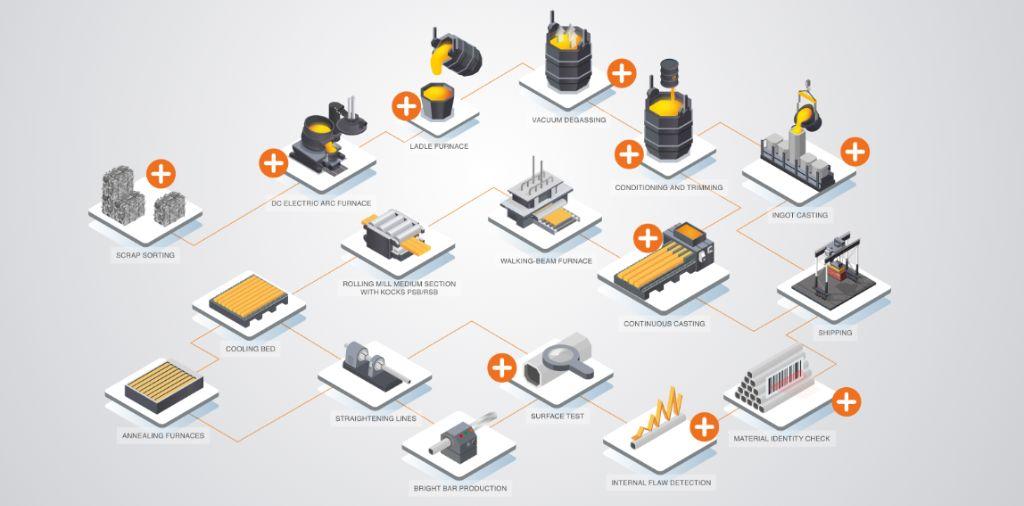
As a steel maker you have several different analysis technologies to choose from. Which one you choose depends on what materials you need to test for, how low the detection limits need to be and the practicality of taking measurements in a busy production environment. We’ll walk through the EAF process from raw material analysis to final QC and discuss which analyzer type is best at each stage and why.
Quick overview of analysis technology
The types of analysis technology I mention here are LIBS, XRF and OES, here’s a very quick overview of each:
X-ray Fluorescence (XRF): A focused beam of X-rays is fired at the surface of the metal. The high energy beam displaces electrons in the atoms and as these electrons fall back into their natural state, they release a very specific energy signature, which the instrument can detect.
Laser Induced Breakdown Spectroscopy (LIBS):A small amount of material on the metal surface is heated with a laser which turns part of the solid metal surface into a very small amount of plasma. As the plasma cools, it emits radiation of a very specific wavelength. Analysis of these wavelengths tells you which elements are present in the sample.
Optical Emission Spectroscopy (OES): Similar in principle to LIBS, but here the metal surface is heated to thousands of ºC with electrical spark discharges. The energy applied causes the atoms in the material to emit characteristic light, which is analysed to determine which elements are present in the sample.
Stage 1: Scrap Sorting
The first analysis step isn’t carried out in the steel mill at all – it’s in the scrapyard. As the main feedstock for steel, the type of scrap for each melt has to be carefully chosen to avoid unwanted impurities entering the melt as much as possible. This means that the scrapyard will select the right type of scrap to meet the melt specification. Using analysis, the scrap needs to be sorted into specific scrap classification classes based on the requirements for the steel grades to be produced. It’s essential that impurities are identified at this stage to avoid unwanted tramp elements ending up in the melt. For example, if a low-phosphorous steel is to be made, then scrap with low phosphorous levels must be chosen.
When it comes to scrap analysis, the most crucial aspects are portability and speed – you really need to be able to take the analyzer to the scrap, not the other way round. Happily, today’s portable and mobile analyzers are extremely accurate, with short analyzing times, and are well within the detection limits for scrap sorting. This is what you can choose from:
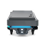
For rapid alloy identification, hand-held LIBS (laser induced breakdown spectroscopy) analyzers are perfect. These, like the Vulcan from Hitachi, are lightweight, truly portable and can identify an alloy grade in seconds. They are perfect for sorting high volumes of scrap.
If, however, you need to measure low levels of sulfur or phosphorous in steel, then you have a choice of two other technologies, XRF (X-ray fluorescence) or OES (optical emission spectroscopy) also known as spark spectrometry. You can use something like the X-MET8000 handheld analyzer that uses XRF technology, or the portable PMI-Master Smart that uses OES.
And if you are selecting scrap based on carbon, nitrogen, boron content, or other elements which must be monitored at very low levels such as copper, tin and lead, then OES technology gives the most accurate reading for these elements.
Stage 2: EAF melt composition and slag analysis
Now we’ll look at the melting and refining process in the electric arc furnace itself. Bath chemistry analysis is carried out once the final scrap charge is fully melted and furnace conditions have stabilised. The results from this test determine how much oxygen needs to pass through during refining. Measurements are also taken at the end of refining, before passing to the next phase.
Here, metals analysis is primarily concerned with detecting phosphorous, sulfur, aluminium, silicon, manganese and carbon as solid impurities, and hydrogen and nitrogen as dissolved gasses.
You may need to take several measurements during the furnace processing until you have removed impurities, such as phosphorous, to the desired level. A dedicated analyzer for EAF melt chemistry analysis is essential for rapid analysis and feedback on processes.
For EAF melt chemistry, because of the low detection limits and element types, OES technology is the one to choose as it’s the only one that is capable of measuring most of these elements at the limits required. Unlike the scrapyard situation, here it’s not essential that the analyzer be portable or mobile. A small sample is taken from the melt and taken to the analyzer, so stationary OES is perfectly sufficient.
Depending on your specific melt chemistry, you’ll need to ensure that the OES instrument you choose can measure all critical elements in metal to the lowest detection limits possible. There’s a huge range of models on the market, from low-end instruments to large lab-based spectrometers. Finding the right one will depend on your needs and your budget. But your starting point should be looking at the detection capability of the instrument.
Slag analysis is important at this stage for two main reasons: Firstly, as the basitivity of the slag can adversely affect the refractory lining of the EAF walls, the slag must be monitored through routine analysis. The second reason is to promote the production of what’s known as ‘foam-slag’. This is where the slag is foamed to increase its volume by forming gaseous carbon oxides. This helps to shield the arc and prevents burning of the steel bath. When done effectively, this process increases thermal efficiency and makes reaching the high temperatures needed for melting much easier. EAF slag is typically comprised of oxidic components, such as CaO, SiO2, and Al2O3,
Stage 3: Secondary processing in ladle furnaces
Specific processing in the ladle furnace – and the analysis that is required as a result – depends on the processing setup of your steel works, but often analysis in secondary processing in ladle furnaces occurs after de-slagging, alloying and vacuum degassing.
One effective step to achieve maximum cleanliness of steel is the use of vacuum technology and purging the material with inert gases. This technology serves to adjust the carbon content, deoxidation, desulfurisation, dephosphorisation and degassing of the liquid steels. Slag process control at this stage is to remove impurities that have not been removed in the EAF.
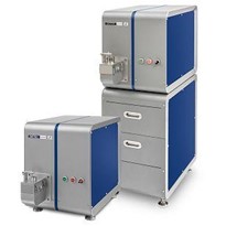
Slag can be analyzed with XRF instruments and wavelength dispersive or energy dispersive instruments are available. For example, in the Hitachi range of energy dispersive XRF equipment, the X-Supreme benchtop analyzer is ideal for slag analysis. This instrument has been optimized for rapid analysis of steel slag and has many other features that are crucial for the steel industry. Minimal dust ingress, high reliability and ease of use are essential in a busy production environment. Other features, such as multi-sample analysis, help to make the analyzer efficient when in 24/7 use.
XRF technology essential for the accuracy required is a powerful X-ray source, high-sensitivity silicon drift detector (SDD) and the ability to take measurements in helium to reduce the effects of interference from the atmosphere. The manufacturer of your XRF equipment will be able to confirm whether the analyser is suitable for the analysis of slag compositions for your specific application.
For alloy analysis, you will need to detect the exact alloy composition and given the range of elements involved and the low levels contained, OES is by far the best technique. And, as in EAF melt chemistry analysis, stationary OES is fine and has been well established over decades as the “workhorse” for routine elemental process analysis.
The final process in the ladle furnace that involves analysis is vacuum degassing. One of the key elements here is hydrogen. It’s necessary to control hydrogen to ultra-low levels in certain types of steel and this is where you’ll need to have the capability to measure hydrogen to very low levels. Gases like oxygen, hydrogen and nitrogen are typically analyzed with combustion analyzers. But modern OES analyzers are able to analyse nitrogen at low levels. However, even among OES analyzers there is a variation in performance, and this is especially true when testing for gasses. For example, in my own product line there is a stationary OES analyzer (OE750) that can analyse nitrogen at low detection limits. Again, check with your own instrument’s manufacturer to see what the detection limits are.
Stage 4: Continuous casting or ingot casting
For continuous casting processes, you’ll need to monitor the composition during mixing a new grade or batch. Again, stationary OES analysis is the essential method. Today’s specifications for plates, wires and rods are complex due to the final applications. Steel wire destined for aerospace or high-performance tyres has very specific requirements and OES is the only technology that can analyse the complete spectrum of elements involved down to the limits required.
OES is also the method you need to choose for process control during ingot casting, and the final steel sample is taken during the casting process for analysis.
Stage 5: Final specification check before shipping
Whether measuring wires, plates, rods or other products from a continuous casting process or individual components from ingot casting, most robust QC programmes will require a final compositional verification check. This is to create a final component composition certificate and to avoid the risk of material mix-up when preparing shipments.
Clearly, we are now dealing with solid, finished components and, like the scrap yard situation, it’s not convenient to take parts to the analyzer for verification. So you have two options: mobile analysis or in-line automation.
Mobile analysis
Depending on actual composition of your components, you can choose between hand-held XRF analyzers, such as Hitachi’s X-MET8000, or mobile OES, like the PMI MASTER range, or the TEST-MASTER Pro that’s specially designed for continuous operation and 100% testing. The XRF hand-held is more portable than the mobile OES and will be ideal for most material verification purposes. However, if you need to verify low alloy steels or light elements such as carbon, boron or other low-level elements that hand-held XRF cannot detect, OES is the best technology to use.
Automation
Many quality control programmes require 100% material testing prior to shipping, and this is where automation can help streamline your testing process and ensure you maintain a steady throughput in your production and a total avoidance of material mix-up. Many OES instruments can be integrated into a production line to provide continuous feedback on final product specification. Products like Hitachi’s own TEST-MASTER Pro OES analyzer are designed specifically for high volume testing on conditioning lines.
Conclusion
Probably the most obvious take-away from this is the need to use more than one analyzer and perhaps more than one technique over the production process. The OES equipment used to determine melt chemistry shouldn’t be tied up with final QC analysis, where a hand-held XRF instrument could do the job more easily. At the end of the day, it’s a question of balancing instrument cost with productivity and accuracy to make sure you are producing a high-quality product, but your analysis doesn’t cause a bottleneck in your process.


-160x160-state_article-rel-cat.png)


-160x160-state_article-rel-cat.png)