The following is a summary of our understanding between the different sensor terminologies.
Pressure Sensors
Today many measuring principles are used in electrical pressure measuring instruments. Most methods are based on the measurement of a displacement or force. In other words, the physical variable "pressure" has to be converted into an electrically quantifiable variable. Unlike mechanical pressure measuring methods, this conversion requires an external power source for the pressure sensor.
This pressure sensor is the basis of electrical pressure measuring systems. While mechanical gauge element displacements of between 0.004 and 0.012 inches are standard, the deformations in electrical pressure sensors amount to no more than a few microns.
Thanks to this minimal deformation, electrical pressure measuring instruments have excellent dynamic characteristics and low material strain resulting in high resistance to alternating loads and long-term durability.
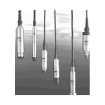
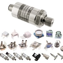
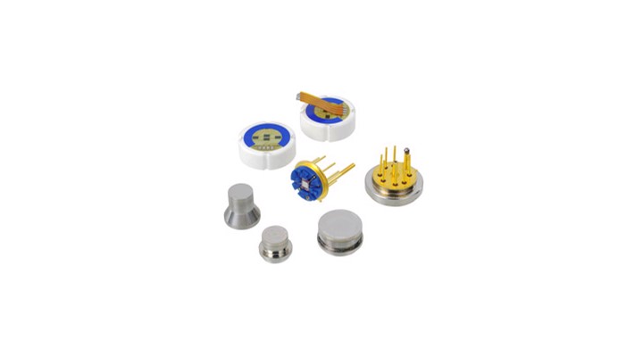
Listed below some of the sensor elements used by WIKA in its electronic pressure measurement instrumentation:
- Capacitive Polymer Sensor
- Ceramic Thick Film Sensor (top left and top middle images)
- Chilled Mirror Sensor
- Electrochemical Sensor
- Infrared Spectroscopy Sensor
- LVDT (Linear Variable Differential Transformer) Sensor
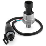
- Piezoresistive (Piezo) Sensor (center and center right images)
- Sound Velocity Sensor
- Thin Film Sensor (bottom left, bottom middle and bottom right images)
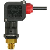
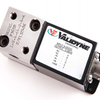
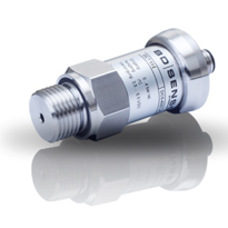
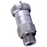
Pressure Transducers
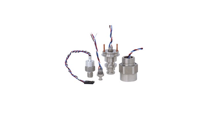
Pressure transducers are an advanced form of pressure sensor element. The simplest form of an electrical pressure measurement system is the pressure sensor. It is the pressure sensor which changes the physical variable "pressure" into a quantity that can be processed electrically. A pressure transducer is the next level of sophistication. In a pressure transducer, the sensor element and housing are in electrical contact and have a pressure connection.
Typical output signals from pressure transducers are between 10 mV and around 100mV, depending on the sensor type. These signals are not standardized, however, nor are they compensated. With thin-film type pressure transducers it is customary for just the sensor element to be welded to the pressure connection and then bonded electrically. Piezoresistive pressure transducers, on the other hand, require far more production steps since the semiconductor sensor element has to be protected from the effects of various media by a chemical seal.
The production of piezoresistive pressure transducers consists of the following steps:
- The elementary sensor is joined to the carrier. TO-8 casings with 8 contact pins and an insulated glass bushing are often used as carriers. The chips are either glued or soldered to the carrier, depending on the manufacturer.
- Then the TO-8 chip is joined to a pressure-bearing case by welding, clamping or soldering.
- The case is then welded to a front diaphragm. This diaphragm is normally designed with corrugations and is approximately 0.1 mm thick. Today some pressure transducers are equipped with plastic diaphragms. Although economical, this material is not compatible with all process media. In most cases the diaphragm is made of stainless steel.
- Next the pressure transducer is filled with a pressure-transmitting liquid (silicone oil). To do this, the pressure transducer is placed in a closed container which is then evacuated. Once the necessary vacuum is reached, the silicone oil is drawn into and completely fills the system without any trapped pockets of air.
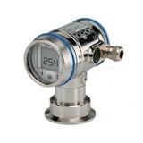
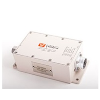
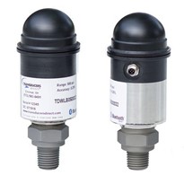
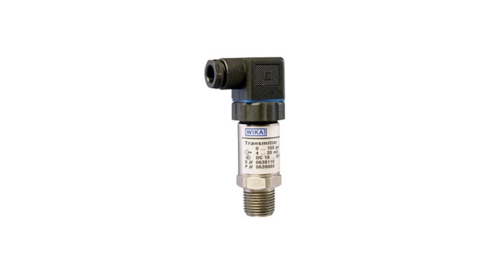
Pressure Transmitters
Pressure transmitters, a sub-group of pressure transducers, feature additional reset and calibration options. With some sensor types it is possible, for example, to re-set the measuring span over large ranges. This calibration option is usually referred to by such terms as "scale down", "span reset" or "turn down". For instance, a transmitter with a measuring range of 0 to 400 psi and a range reset 1/10 can be calibrate to a measuring range of 0 - 40 psi while still giving a full output signal (4 - 20 mA, for example).
It is also possible to shift the zero point over a wide range and to calibrate the damping of the output signal between 0 and 32 seconds. Smart transmitters such as Hart®, which also have logging capabilities, can be calibrated, tested and reset via the control desk or hand terminals.
Transmitters are often used in process applications where they can be combined with various chemical seals.