A growing level of attention has recently been given to the automated control of potentially hazardous processes such as the overpressure or containment of dangerous substances. Several independent protection methods provide measures to reduce the risk from such hazards to personnel, the environment and assets. A significant level of this risk reduction is allocated to safety instrumented functions (SIF).
The integrity of the safety instrumented system (SIS) to perform these functions (known as functional safety) is therefore critical and the requirements for determining and achieving functional safety are given in IEC 61511-1. This standard is now adopted as the predominant worldwide standard for such systems in the process industry.
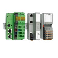
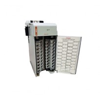
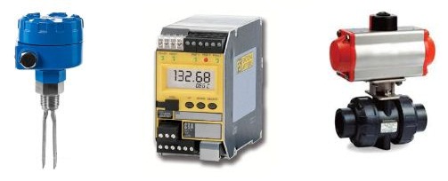
The integrity requirements of the SIS have implications on all the elements that comprise the system such as sensors, interfaces, controllers, logic solvers, actuators and valves. All the connections that make up the complete control loop are also taken into consideration. One of the key instruments in this loop is the logic solver (decision maker), which initiates the final element to make the process safe if the need arises.
The aim of this paper is to explore some of the possibilities available to the SIS designer of a tank overfill protection system for the logic solver and to show examples of straightforward system topologies and their associated safety integrity level (SIL) calculations. A general step-by-step procedure to define and evaluate an SIS is suggested in the Appendix. The examples used in this paper illustrate how the procedure is applied in specific cases.
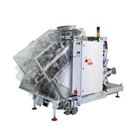
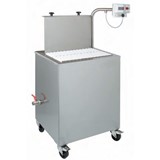
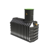
Tank Overfill Protection System
A tank overfill protection system is a SIS that provides an additional layer of protection over the basic tank gauging (control) system. As with all SIS, the actual SIL needs to be established for the particular tank at the storage facility, taking into account all the operational risk factors, but typically these functions are SIL 1 or 2. It is important that the instrumentation used in the SIS is totally independent from that used in the tank gauging system so that it does not suffer interference from the latter or be subjected to common points of failure.
It is expected that the overfill protection function automatically shuts off the input feed to the tank by isolating the pump and closing the input valve (ensuring that any resulting pipeline pressure surges are suitably dealt with). Tank level sensors can be degraded over time due to their exposed position both inside and outside the tank, and it is advantageous to use devices that have diverse technologies from the tank gauging sensors.
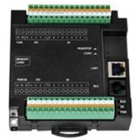
Factors Leading to the Choice of a Logic Solver
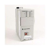
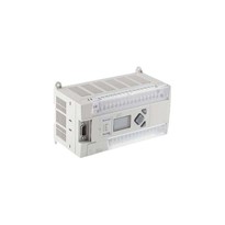
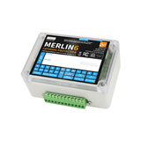
People can often assume the logic solver has to be a safety PLC. But in many cases a discrete logic device for each loop, which avoids the complications and expense of a programmable solution, is a sensible option. One of the objectives of functional safety is to engineer the protection layers so that the complexity of safety-related functionality is minimised.
This includes designing the overall concept for the minimum number of safety instrumented loops, avoiding the unnecessary use of more complex technology and reducing interdependency between loops and keeping safety and non-safety functionality separate. IEC 61508-2 and related standards demand a higher burden on the architectural design, which can often be avoided using less complex discrete logic solver technologies.
Apart from the obvious savings in cost from a simpler architecture, perhaps the biggest gains with this approach are unseen. Consider that this straightforward approach avoids the development cost of application programming (plus associated costs such as software maintenance, upgrades, configuration management and back-ups) and the need for specialist competence in operation and maintenance of the programmable platform.
Installation, validation and commissioning of complex programmable systems also require specific competence and procedures, which can make the functional safety management (FSM) system more onerous to set up and maintain.
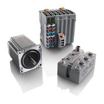
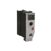
Many safety-related applications in the process industry are ideally suited to one or more single loop logic solvers because they are small scale, isolated or located in remote areas. As mentioned, the simpler architectural demands using this approach can reduce the cost of hardware, software and procedural overheads.
Read the complete white paper