
GEAR QUALITY CONTROL INTRODUCTION
Australian businesses design and manufacture gears of various sizes and tolerance requirements for industries including automotive, transportation, power generation and more.
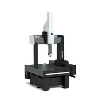
Traditionally, gears are inspected using manual gauges or CMMs. Gauges and manual tools tend to be prone to human error as well as being highly inaccurate and not allowing for automated digitisation of results and reports. Although highly accurate, CMMs represent heavy capital investments as well as providing slow and limited, point-based measurement results.
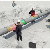
By using optical metrology systems, gear inspection can be sped up while maintaining a high degree of accuracy and providing data on the whole part instead of individual points as a CMM would. Furthermore, optical systems offer many benefits for large scale objects as you will see below.
GEAR 3D INSPECTION TOOLS & PROCESSES
The video bellow highlights the gear quality control inspection process from start to finish.
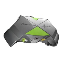
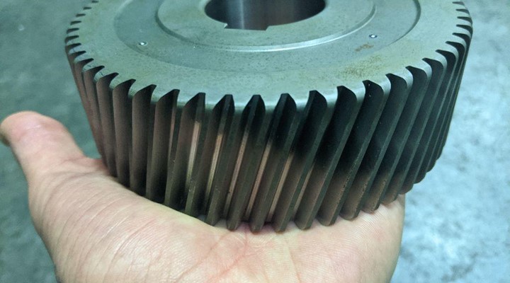
Step 1: part preparation using AESUB Scanning Spray
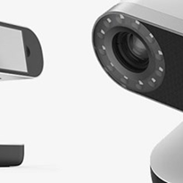
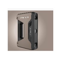
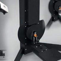
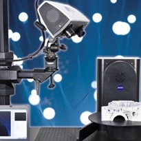
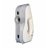
Step 2: 3D scanning using the ATOS Q optical sensor & GOM Rotary table for automation
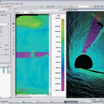
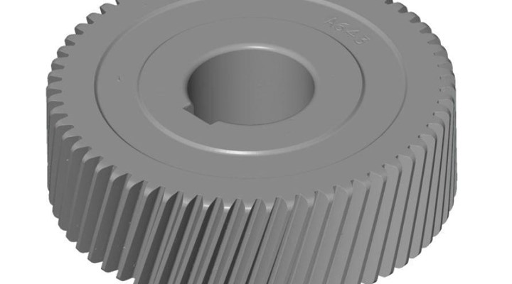
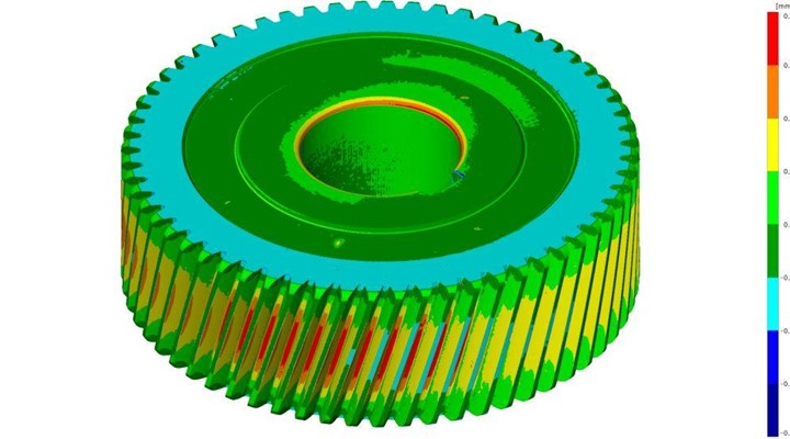
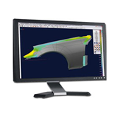
Step 3: GOM Inspect was used to render mesh data and perform inspection and analyses
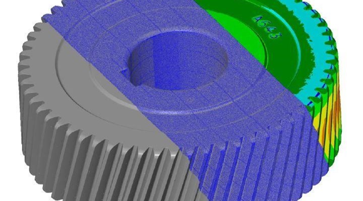
GEAR QUALITY CONTROL RESULTS
Many key parameters can be analysed directly in the software allowing operators to quickly spot defects and perform quality check. Reports can be automatically created for client quality assurance and traceability purposes.


-205x205.jpg)