
In this new landscape, wavelength division multiplexers (WDMs) and fibre optic rotary joints (FORJs) will play pivotal roles. This article will describe the basics of optical fibre, WDM technologies, FORJs, and their untapped potential in changing the industry's way of thinking. The article can also serve as a practical guide for the design of new fibre-based undersea systems.
Optical Fibre vs. Copper Wire
Over the past three decades fibre has become the transporting medium of choice for voice, video, and data, particularly for high-speed communications. Fibre is compact, low-loss, immune to electromagnetic interference, secure, non-corrosive, and has almost unlimited bandwidth. Let us focus on a few key characteristics.
Wide bandwidth:
Optical fibre has been proven to have the widest bandwidth compared to any other media known, including wireless, copper wire, sonar, and even free-space-optics. Tera Hertz (10 to the 12th power) bit rate has been demonstrated in the lab by using the standard singlemode telecom fibre.
As a comparison, the entire useful radio bandwidth worldwide is only 25Gbps, a mere 0.1 percent of the bandwidth supported by a single strand of fibre. As a result, a single strand of optical fibre can easily replace a large bundle of copper wires while significantly boosting system bandwidth.
Low loss:
Optical fibre poses far lower loss to signal than any other transmission media. The typical loss per kilometer in a singlemode fibre is around 0.4dB at any bit rate, making it possible to send signal over a much longer distance (more than 100km) without the need for repeaters or amplifiers. On the contrary, the typical loss figure for a coaxial copper cable is around 40dB/km at 10-100Mbps and grows linearly with bit rate.
High security:
Unlike its copper counterparts, an optical fibre does not emit electromagnetic waves and therefore is extremely difficult to tap into. Even if the fibre were tapped into, it would create enough disturbance in the system to be detected. Therefore, optical fibre has been the most preferred transmission medium in secure systems worldwide, particularly military applications.
Increased safety:
Electrical current can be extremely harmful in an environment where flammable or explosive materials are used or stored. Optical fibre provides an ideal channel to collect useful information such as temperature, pressure, and humidity in these environments.
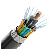
Singlemode vs. Multimode Fibres
A typical single strand of optical fibre consists of the silica core doped with rare earth element, the silica cladding, and a layer of protective jacket, typically acrylic. The core diameter and its index of refraction relative to the cladding determine the mode structure of the beam. The standard singlemode telecom fibre core diameter is around nine microns. The two most popular multimode fibre diameters are 50 and 62.5 microns.
The selection of fibre primarily depends on the system's current and, more importantly, its future need for bandwidth. Multimode fibre has limited bit rate, up to 100Mbps for lengths up to 40km; shorter lengths support higher bit rates. Standard singlemode fibre supports up to tera bits per second over 100km without amplification.
If one can be confident that the need for bandwidth is not going to exceed a few hundred megabits-per-second over a short distance in the lifetime of the system, then multimode should be the choice for lower cost. However, if any branching device (such as a coupler) was necessary in the system, singlemode fibre is recommend for its much better stability in branching devices. Keep in mind that singlemode systems have been growing much faster than multimode systems due to their much higher level of upgradeability.
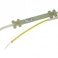
Multiple Multiplexers
Time division multiplexing (TDM) and wavelength division multiplexing (WDM) both use single fibres to transmit multiple streams of signal traffic. TDM allocates traffic streams to separate time slots, while WDM carries each on a separate wavelength. TDM technology can carry 2.44 Gbps (OC-48) per fibre, but WDM can support 2.44 Gbps per wavelength-and from 2 to >40 wavelengths per fibre near 1550 nm window alone.
The difference between course wavelength division multiplexer (CWDM) and dense wavelength division multiplexer (DWDM) appears in channel spacing. DWDM is generally defined to have channel spacing of 4nm or less, while CWDM typically has 20nm.
The 16 standard CWDM channels defined by ITU are: 1470, 1490, 1510, 1530, 1550, 1570, 1590, 1610nm (in accordance with the ITU-T.694.2 CWDM grid); and 1310, 1330, 1350, 1370, 1390, 1410, 1430, and 1450nm (in accordance with the ITU-T.694.2 CWDM grid).
There are also eight popular CWDM channels near 850nm: 778, 789, 800, 812, 825, 837, 850, and 864nm (in accordance with IEEE 802.3z standard).
The most important advantage of CWDM is that the laser sources do not require temperature control and therefore system cost is greatly reduced. Due to the limited bandwidth requirement of a typical undersea telemetry system, it is very unlikely that a DWDM system is necessary. Even if the bandwidth need outgrows the CWDM capacity in the future, the system can be upgraded without replacing the fibre cable.
Traditional WDM technology relies on multiplexing 850nm and 1310nm or 1310nm and 1550nm to increase system bandwidth. In recent years the 1550nm window has become increasingly popular thanks to the low chromatic dispersion figure and the availability of wide variety of DWDM components in not only the C band (1530-1570nm), but also the two adjacent bands, S (1490-1530nm) and L (1570-1620nm).
Using WDM, CWDM, or DWDM technology can multiply the system's capacity more than 100-fold without adding any additional fibres. With so many channels and so much bandwidth available, one can easily multiplex all digital and analog signals into a single fibre in a typical ROV system. However, multiple fibres are often considered for redundancy purpose.
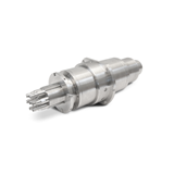
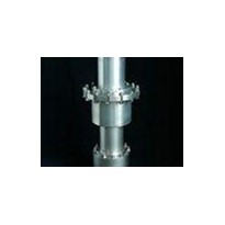
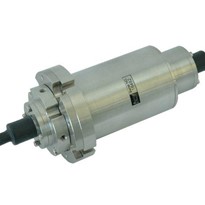
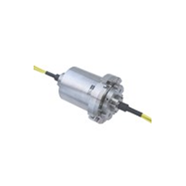
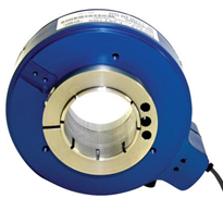
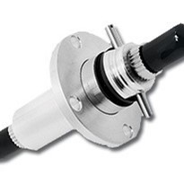
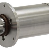
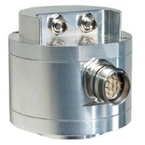
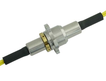
Fibre Optic Rotary Joints
Fibre optic rotary joints (FORJs), sometimes called fibre optic slip rings, play pivotal roles in an undersea ROV system with fibre telemetry. However, all FORJs are not the same. They differ in mechanical structure and optical design, and therefore in performance. The following are key characteristics for a FORJ:
Insertion Loss:
A 3dB insertion loss is equivalent to 50 percent transmission. As one can imagine, it can cut into the overall optical budget significantly if the insertion loss is not maintained below this level. In a high optical power system (1-4 W), any loss more than 2-3dB could result in significant device heating and subsequent failure.
Insertion Loss Variation:
It is natural to experience some loss variation as the FORJ rotates due to changing coupling conditions. However, if this variation reaches a certain level, signal-to-noise ratio degrades. A 0.5dB maximum is the best commercially available. Return Loss: All laser sources, especially distributed feedback lasers, are sensitive to optical reflection, which causes spectral fluctuation and, subsequently, power jitter.
Return loss is a measure of the amount of reflection accruing in an optical system. A -45dB reflection is equivalent to 45dB return loss. A minimum of 45-50dB return loss is the industry standard for passive components to ensure normal system operation in singlemode fibre systems.
Optical Bandwidth:
Like most other passive fibre optic components, many FORJs have limited spectral width. Recently, a new design promises the entire spectral width of the optical fibre. Therefore, it is possible to multiplex all three optical bands from 850nm to 1550nm.
Packaging styles:
Pigtailed FORJs are highly recommended for their consistent optical performance and longevity. The optical performance of a receptacle type of FORJ depends heavily on the mating connector. Performance degradation is also common in receptacle type of devices. Dust particles and moisture introduced by repeated mating are the main cause of problems.
Connector types:
For historical reasons, ST connectors have been the workhorses in FORJ applications even though they are known to have inferior optical performance. Furthermore, ST connectors cannot be polished at an angle for a better return loss figure. Our recommendation is FC connector, which is the most popular connector type in the telecommunication industry. The eight-degree angle polished FC/APC (angled physical contact) is also readily available. SC, SC/APC, LC, and LC/APC are a few other popular connector types.
Size:
If the history of fibre optic components over the past decades is any indication, FORJs will become smaller. A compact FORJ needs smaller torque to rotate, occupies smaller space, and promises much easier integration with electrical slip rings.
Selecting the wrong type of FORJ can often cause serious performance issues in the system. For example, the most common cause of optical power or frequency jitter is high reflection or back scattering, which is often referred to as low return loss.
A laser is essentially an optical oscillator with a fixed oscillation frequency (wavelength). Optical reflection or back scattering tends to push or pull the optical frequency around its natural peak. In turn, optical power would fluctuate according to the laser gain profile.
The best solution is to identify the optical component (such as the FORJ) that has low return loss and replace it with a high performance unit and replace all ST connectors with FC/APC connectors.
All-Fibre Telemetry without Local Power Source?
Even with a core diameter as small as nine microns, standard singlemode fibre is capable of carrying optical power well exceeding the 1W level. Multimode fibres can have kW level optical power handling capability. With the increased efficiency of photovoltaic devices, an all-fibre telemetry system in the absence of a local power source is not just a dream anymore.
For example, equipped with a solar cell at greater than 20 percent efficiency, one can obtain 2W of electrical power in the remote location by sending a 10W laser beam from the station, enough to power a typical sensor, actuator, or a small camera.
The temporary decline of the telecommunications market has left the undersea exploration industry a historical opportunity to transform itself from bulky, low speed, all-electrical telemetry to partially-fibre or wholly-fibre telemetry. The field is filled with standard WDM components and systems at much reduced cost.
For example, a passive, all-fibre 1310/1550nm WDM can be purchased off the shelf for as little as $50-$100. New FORJ products are also emerging with much improved performance, greatly reduced size, and better availability. So stop wondering, embrace the new technology, and become a leader.